USB Headers on a Motherboard Explained
A USB header is an internal motherboard connector, typically 9, 19, or 20 pins, that links front-panel USB ports and internal devices to the system’s USB bus.
Last updated: July 2026
Table of Contents
- Quick Answer: What Is a USB Header on a Motherboard?
- What Does a USB Header Do?
- The Role of the Internal USB Header in a PC Build
- USB Header vs. Rear Panel USB Ports, What’s the Difference?
- Types of USB Headers, Every Standard Explained
- USB 2.0 Header (9-Pin)
- USB 3.0 / USB 3.2 Gen 1 Header (19-Pin)
- USB 3.2 Gen 2 / Type-E Header (20-Pin)
- Master Comparison Table, All USB Header Types
- USB Header Pinout, What Each Pin Does
- USB 2.0 9-Pin Header Pinout
- USB 3.0 19-Pin Header Pinout, Key Signals
- Why Pinout Matters for Builders
- How Many USB Headers Does a Motherboard Have?
- USB Header Compatibility, Does It Matter Which One You Use?
- Matching Your Case Cable to Your Motherboard Header
- What Happens When You Have a Mismatch? (Adapters Explained)
- Where to Find USB Headers on a Motherboard
- Troubleshooting Common USB Header Problems
- Front Panel USB Port Not Working, Diagnosis Steps
- USB Header Causing Boot Issues or POST Failures
- No USB Header Available, Expansion Options
- FAQ, USB Headers Explained
- What does a USB header do?
- What do USB headers look like?
- Does it matter which USB header you use?
- Where does the USB 3.0 header go on a motherboard?
- Can I add more USB headers to my motherboard?
- The Short Version
Quick Answer: What Is a USB Header on a Motherboard?
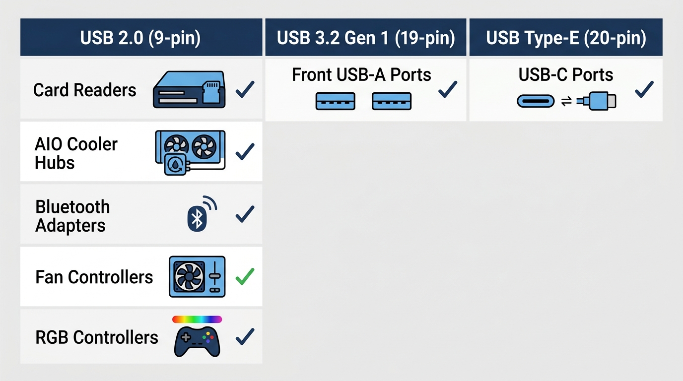
A USB header (also called a motherboard USB header or internal USB header) is a keyed pin connector soldered onto the PCB that carries both power and data between your motherboard’s USB controller and components like front-panel USB ports, AIO cooler hubs, card readers, and RGB controllers. It is not accessible from outside the case. You connect it using a matching cable from your case or internal device. There are three main types: 9-pin (USB 2.0), 19-pin (USB 3.2 Gen 1), and 20-pin Type-E (USB-C).
Most people assume the USB ports on the front of their PC case connect directly to the motherboard’s USB controller chip. They don’t. Every front-panel USB port you see on your case runs a cable to an internal USB header buried on the PCB. Get the header wrong, and those ports don’t work. Buy a case with a USB-C front panel when your board lacks a Type-E header, and you need an adapter or expansion card. Understanding which headers your motherboard has before buying a case saves you real headaches.
- 🟢 USB 2.0 (9-pin, black): Safe for any internal USB device, fan controller, card reader, or legacy front panel. 480 Mbps max.
- 🟢 USB 3.2 Gen 1 (19-pin, blue): Standard for modern case front panels. 5 Gbps. Present on nearly all ATX and mATX boards.
- 🟡 USB 3.2 Gen 2 Type-E (20-pin): Required for front-panel USB-C ports. Not present on all boards. Verify before buying a case with USB-C.
- 🔴 Mismatched connector: Physically impossible to connect without an adapter. Never force a connector.
- 🔴 Bent pin on USB 2.0 header: No keying on older cables. A single bent pin kills both ports on that header.
What Does a USB Header Do?
The Role of the Internal USB Header in a PC Build
The USB header bridges your motherboard’s USB controller chip and any USB port or device that isn’t soldered directly to the rear I/O panel. It carries two things simultaneously: 5V power and differential data signals. Without it, your case’s front USB ports are just plastic shells with nowhere to go.
Devices that connect through internal USB headers include front-panel USB-A and USB-C ports, built-in card readers, all-in-one liquid cooler control boards, internal Bluetooth adapters, fan and RGB controllers, and USB-connected NVMe enclosures in some workstation cases. One overlooked advantage: USB headers support hot-swapping. You can plug and unplug devices from ports routed through a header without restarting the system. The USB controller handles enumeration dynamically.
USB Header vs. Rear Panel USB Ports, What’s the Difference?
Rear panel ports are physically soldered onto the PCB itself and connect directly to the USB controller with traces etched into the board. Internal USB headers route the same signals through a pin connector and a short ribbon or cable run to wherever the port physically lives. That’s the only real difference.
Speed is not one of the differences, despite what you might assume. A USB 3.2 Gen 1 front-panel port connected through a 19-pin header delivers the same 5 Gbps as a rear USB 3.2 Gen 1 port. The cable adds negligible signal path length. Latency difference is in the nanosecond range. Unmeasurable in practice. The only scenario where you see a speed penalty is when you’re using an adapter to connect a higher-spec case cable to a lower-spec header, which caps throughput at the slower standard. For a deeper look at how USB 2.0 and 3.0 speeds compare in real use, the USB 2.0 vs 3.0 differences guide breaks it down with practical benchmarks.
| Feature | USB Header (Internal) | Rear Panel USB Port |
|---|---|---|
| Connection type | Pin header + cable | Directly soldered to PCB |
| User-replaceable | Yes (via cable) | No |
| Typical location | Near PCB bottom edge | I/O shield backplate |
| Max speed potential | Up to 20 Gbps (Type-E Gen 2×2) | Up to 40 Gbps (USB4 on high-end boards) |
| Common use | Front panel, internal devices | Keyboards, mice, external drives |
Types of USB Headers, Every Standard Explained
This is where builders get confused. USB naming has been rebranded multiple times, the physical connectors look similar at a glance, and not every board has every type. Here’s what each header actually is.
USB 2.0 Header (9-Pin)
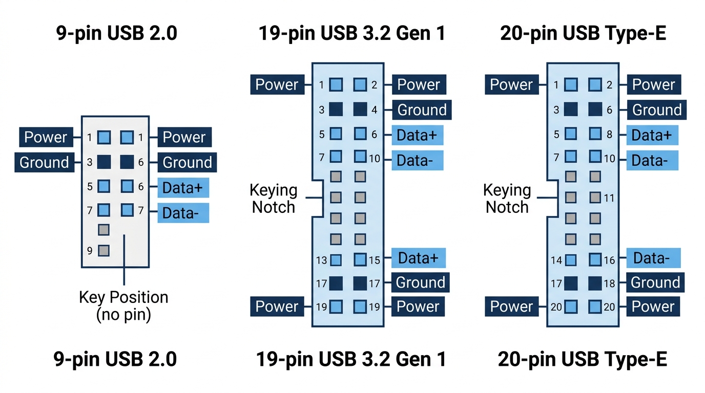
Still present on almost every motherboard shipping in 2026, the 9-pin USB 2.0 header is the smallest and most common internal USB header you’ll encounter. It uses a 2×5 grid layout with one pin deliberately absent to act as a key.
- Pin count: 9 (2×5 layout, one pin removed for keying)
- Max speed: 480 Mbps (USB 2.0 High Speed); backward compatible with USB 1.1 at 12 Mbps
- Ports per header: 2 USB-A ports
- Voltage: 5V, 500mA maximum per port
- Housing color: Typically black
- Footprint: Approximately 12mm x 8mm
- Common uses: Fan controllers, RGB hubs, card readers, older case front panels, internal Bluetooth adapters
480 Mbps is plenty for most internal devices. Your AIO cooler’s USB hub, your ARGB controller, your internal card reader, none of them push anywhere near that ceiling. Don’t stress about the 2.0 header being “slow” for those use cases. Not a problem.
USB 3.0 / USB 3.2 Gen 1 Header (19-Pin)
The naming history here is genuinely confusing. USB 3.0, USB 3.1 Gen 1, and USB 3.2 Gen 1 all refer to the same 5 Gbps specification. It’s been rebranded twice. The connector and header haven’t changed.
- Pin count: 19 (dual-row housing)
- Max speed: 5 Gbps
- Ports per header: 2 USB-A ports
- Voltage: 5V, 900mA maximum per port
- Housing color: Blue (industry standard)
- Footprint: Approximately 28mm x 11mm
- Common uses: Main case front-panel USB-A ports on modern cases
This is the header that powers the large USB-A port on the front of most mid-tower cases. If your case ships with a single thick blue connector cable, this is where it goes.
USB 3.2 Gen 2 / Type-E Header (20-Pin)
The Type-E header is what you need when your case has a front-panel USB-C port. It’s a compact 20-pin square connector, keyed differently from the 19-pin USB 3.0 header, and it physically cannot be confused with the others. It was introduced around 2019 on mid-to-high-end boards and has since become standard on anything above entry-level in 2026.
- Pin count: 20 (USB Type-E connector, also called internal USB-C header)
- Max speed: 10 Gbps (Gen 2) or 20 Gbps (Gen 2×2, on select boards)
- Ports per header: 1 USB-C port
- Voltage: 5V/9V/15V/20V with USB Power Delivery support
- Common uses: Front-panel USB-C ports on modern cases (Fractal Torrent, Lian Li Lancool 216, and similar)
Not backward compatible with the USB 3.0 19-pin header without an adapter. The connector shapes are entirely different. Worth verifying this header exists on your board before buying a case with a USB-C front panel.
A small note on USB4: select high-end boards in 2026, including the ASUS ProArt line and MSI MEG series, include USB4 headers capable of 40 Gbps. These are rare and use their own connector standard distinct from Type-E.

Master Comparison Table, All USB Header Types
| Header Type | Pin Count | Max Speed | Ports per Header | Voltage | Backward Compatible With |
|---|---|---|---|---|---|
| USB 2.0 (9-pin) | 9 | 480 Mbps | 2x USB-A | 5V / 500mA | USB 1.1 |
| USB 3.2 Gen 1 (19-pin) | 19 | 5 Gbps | 2x USB-A | 5V / 900mA | USB 2.0 (via adapter) |
| USB 3.2 Gen 2×1 Type-E (20-pin) | 20 | 10 Gbps | 1x USB-C | Up to 20V PD | No direct backward compat. |
| USB 3.2 Gen 2×2 Type-E (20-pin) | 20 | 20 Gbps | 1x USB-C | Up to 20V PD | USB 3.2 Gen 2 Type-E |
USB Header Pinout, What Each Pin Does
Most guides mention that USB headers have pins and leave it at that. Here’s what each pin actually carries, and why it matters when you’re troubleshooting or working with older cases that use separated individual-pin connectors.
USB 2.0 9-Pin Header Pinout
| Pin | Signal | Description |
|---|---|---|
| 1 | VCC | +5V Power (Port 1) |
| 2 | VCC | +5V Power (Port 2) |
| 3 | D− | Data Negative (Port 1) |
| 4 | D− | Data Negative (Port 2) |
| 5 | D+ | Data Positive (Port 1) |
| 6 | D+ | Data Positive (Port 2) |
| 7 | GND | Ground (Port 1) |
| 8 | GND | Ground (Port 2) |
| 9 | KEY | Missing pin, prevents incorrect insertion |
The missing pin 9 is a physical safeguard built into the header itself. It prevents a standard 2×5 cable block from being inserted backwards. However, older cases supply individual 2-pin or 4-pin connectors that you seat manually, one at a time, with no such protection. Reversing polarity on those, specifically putting 5V on a data line, can damage the connected device and potentially the USB controller. Always check the silkscreen on the PCB for pin 1 orientation before seating manual connectors. Your motherboard manual will show a pinout diagram, usually in the first few pages of the I/O section.
A single-port 5-pin variant of this header exists on some boards as well. It uses only pins 1, 3, 5, 7, and the key position, supporting one USB-A port instead of two.
USB 3.0 19-Pin Header Pinout, Key Signals
The 19-pin USB 3.0 header is significantly more complex. It carries the complete USB 2.0 signal set (covering backward compatibility) plus SuperSpeed differential pairs for each port. Key signal groups include:
- VBUS (pins 1, 19): +5V power, one pin per port
- StdA_SSRX−/StdA_SSRX+ (pins 2−3, 17−18): SuperSpeed receive differential pairs, one pair per port
- StdA_SSTX−/StdA_SSTX+ (pins 5−6, 14−15): SuperSpeed transmit differential pairs, one pair per port
- USB 2.0 D−/D+ pairs (pins 8−9, 11−12): Legacy data lines for USB 2.0 device compatibility, one pair per port
- GND / GND_DRAIN (pins 4, 7, 13, 16): Ground and shield-drain return lines
- KEY (pin 20, unpopulated): Missing pin position that enforces correct orientation
The USB-IF publishes the full electrical specification for USB 3.2 at usb.org/document-library. It’s dense, but the pinout tables in Section 3 are the authoritative reference if you’re working on a custom cable or troubleshooting signal integrity issues.
Why Pinout Matters for Builders
For most builds with modern keyed cable assemblies, you don’t interact with individual pins at all. Seat the connector, done. Where pinout knowledge becomes relevant:
- Older cases with individual-pin USB 2.0 connectors: You have to seat each pin manually, and polarity matters.
- Troubleshooting bent pins: Knowing which pin carries 5V vs. data helps you identify whether a bent pin will cause a dead port or a potential short.
- Custom cable fabrication: Building a custom internal USB hub or panel requires matching each signal correctly.
How Many USB Headers Does a Motherboard Have?
Header count varies significantly by chipset tier and form factor. Budget boards do cut corners here, and it’s worth checking before you assume your case’s front panel will be fully functional. Here’s what to expect from current-generation boards in 2026:
| Board Tier | Form Factor | USB 2.0 Headers | USB 3.2 Gen 1 Headers | USB 3.2 Gen 2 Type-E |
|---|---|---|---|---|
| Budget (B650, B760, B860) | ATX | 1–2 | 1 | 0–1 |
| Mid-range (B650E, Z790, Z890) | ATX | 2 | 1–2 | 1 |
| High-end (X670E, X870E, Z890 Apex) | ATX | 2–4 | 2 | 1–2 |
| Compact | Mini-ITX | 1 | 1 | 0–1 |
Mini-ITX boards sacrifice header count to fit the 170x170mm PCB constraint. If you’re planning an ITX build and want a USB-C front panel, confirm the Type-E header is present before ordering. Not always a given at that size. AMD’s X870E and X870 chipsets on current Ryzen 9000 series boards generally include a Type-E header even at mid-range pricing, which is a welcome improvement over older B550 and X570 boards that often skipped it entirely. You can check AMD’s Ryzen product specifications to cross-reference chipset-level USB allocations.
USB Header Compatibility, Does It Matter Which One You Use?
Matching Your Case Cable to Your Motherboard Header
The physical connector shapes on USB headers are deliberately incompatible across generations. A USB 3.0 19-pin case cable won’t fit a USB 2.0 9-pin header. Period. The connectors are different sizes and key positions, so you can’t accidentally plug the wrong thing in. Modern assembled cables make this essentially foolproof.
The exception is older cases that supply individual 2-pin connectors for each USB 2.0 signal pair. Those individual connectors have no physical safeguard and can be seated incorrectly. Always consult the motherboard manual when working with these.
What Happens When You Have a Mismatch? (Adapters Explained)
The scenario builders hit most often: a modern case with a USB 3.0 19-pin front-panel cable and a budget board that only has USB 2.0 9-pin headers. Or a case with a USB-C front panel and a board without a Type-E header. Adapters solve both problems, with a speed cost.
| Case Cable | Board Header Available | Adapter Needed | Resulting Speed |
|---|---|---|---|
| USB 3.0 (19-pin) | USB 2.0 (9-pin) only | Yes, 19-pin to 9-pin adapter | 480 Mbps |
| USB-C Type-E (20-pin) | USB 3.0 (19-pin) only | Yes, Type-E to 19-pin adapter | 5 Gbps |
| USB-C Type-E (20-pin) | No header available | PCIe USB expansion card | 5–10 Gbps |
| USB 2.0 (9-pin) | USB 3.0 (19-pin) only | Yes, 9-pin to 19-pin adapter | 480 Mbps |
Adapters are inexpensive, typically $5 to $15 from brands like StarTech and Delock, and they work reliably. The port functions, just at the lower standard’s speed. If you’re routing USB 3.0 through a 2.0 adapter, don’t expect to hit 5 Gbps transfer rates. That ceiling drops to 480 Mbps regardless of what device you plug in.
Motherboard RGB and ARGB controllers often connect through USB 2.0 headers. If you’re running out of USB 2.0 headers for lighting control alongside front-panel ports, a splitter cable or additional headers via PCIe expansion card are both practical solutions. The RGB header guide covers how different lighting connectors share the same USB infrastructure on most boards.
Where to Find USB Headers on a Motherboard
USB headers are always somewhere near the bottom edge of the PCB, placed there to minimize cable run length to the case’s front panel. Here’s where to look for each type:
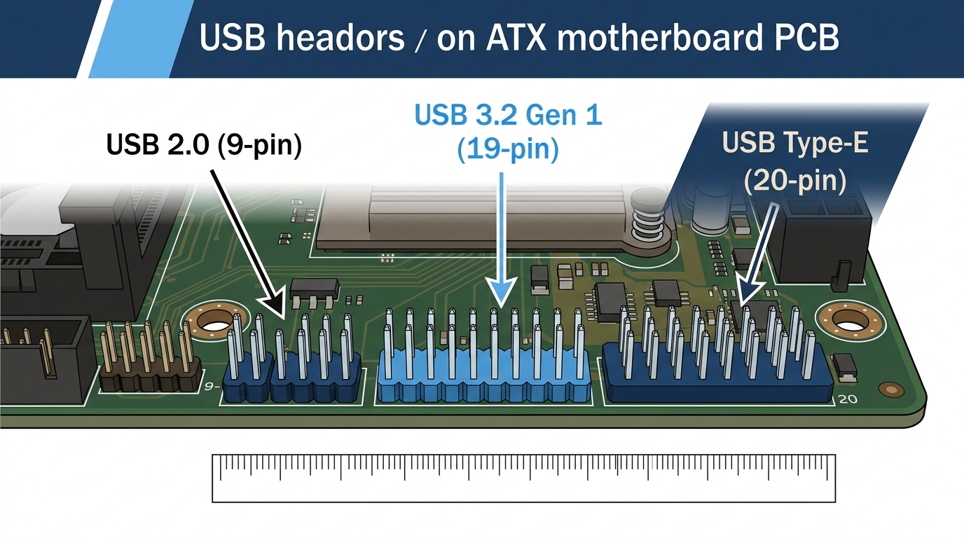
- USB 2.0 (9-pin, black): Bottom-right area, clustered near front-panel connectors like the power button header and front panel audio (AAFP). Usually labeled JUSB1 or JUSB2 in the PCB silkscreen.
- USB 3.0 (19-pin, blue): Lower-left or lower-right edge, often adjacent to SATA ports. The blue housing and larger footprint make it easy to identify by sight. Typically labeled USB3_12, USB3_34, or F_USB3.
- USB Type-E (20-pin): Often near the PCIe slots or bottom-center of the board. Labeled JUSB_C1 or similar. Always check your manual since placement varies more than the other header types.
The PCB silkscreen labels are small but present on every board. If you’re squinting at the board without a manual handy, the easiest identification method is color and size: black and small means USB 2.0, blue and larger means USB 3.0, and a compact square block is Type-E. When in doubt, page one or two of your motherboard manual’s I/O layout section will show an overhead diagram with every header labeled by function. Intel’s documentation for the Z890 chipset, available on Intel’s chipset product page, also confirms USB allocation per platform if you want to cross-check specifications.
Troubleshooting Common USB Header Problems
Front Panel USB Port Not Working, Diagnosis Steps
Front panel USB failures almost always have one of five causes. Work through these in order:
- Check seating: USB 3.0 19-pin connectors require firm, deliberate pressure to seat fully. They’re tighter than USB 2.0 connectors by design. A partially seated connector produces intermittent or dead ports.
- Verify correct header: Confirm the cable type matches the header it’s connected to. A USB 3.0 cable on a USB 3.0 header, USB 2.0 cable on a USB 2.0 header. Physically impossible to mix them up with modern keyed connectors, but worth confirming for older cases with individual-pin setups.
- Check BIOS USB configuration: Some boards ship with internal USB headers disabled in firmware. Go to Advanced > USB Configuration and confirm internal headers are enabled. This is more common on workstation-tier boards than consumer ones.
- Test with a different device: Rules out a dead device rather than a dead port.
- Inspect header pins: A single bent pin on a USB 2.0 header kills both ports serviced by that header. Use a magnifying glass and good lighting. Bent pins are straighter than you think and easy to miss.
USB Header Causing Boot Issues or POST Failures
Rare, but documented. A shorted USB header, where a bent pin contacts an adjacent pin, can prevent the system from completing POST. If your PC won’t boot and you have internal USB devices connected, disconnect all internal USB headers and attempt a boot. If it posts, reconnect one header at a time to isolate the problem connector.
Also check device current draw. USB 2.0 headers supply 500mA per port maximum. USB 3.0 headers supply 900mA. A power-hungry device, such as a portable drive or USB hub drawing more than the rated current, can cause instability or hard shutdowns. Check the device’s USB power specification against the header’s rated output.
No USB Header Available, Expansion Options
If you’ve run out of headers, two options cover most situations:
- PCIe USB expansion card: Installs in any available PCIe slot and adds 2x 9-pin USB 2.0 headers or a 19-pin USB 3.0 header. StarTech and Delock both make reliable options in the $15 to $30 range.
- USB header splitter cable: Splits one USB 2.0 9-pin header into two. The bandwidth is shared between both ports. Sufficient for low-data-rate devices like RGB controllers and internal card readers, not for storage.
FAQ, USB Headers Explained
What does a USB header do?
A USB header connects internal components to your motherboard’s USB bus, supplying both power and data transfer capability. Your case’s front-panel USB ports, AIO cooler control boards, card readers, and internal Bluetooth adapters all connect this way. Without a header connection, those devices have no communication path to the rest of the system.
What do USB headers look like?
USB 2.0 headers are small black 9-pin connectors arranged in a 2×5 grid near the bottom edge of the motherboard. USB 3.0 headers are larger blue 19-pin dual-row connectors with a distinctive plastic housing. USB Type-E headers are compact 20-pin square connectors used for front-panel USB-C ports and are keyed differently from the other two types. All three are labeled on the PCB silkscreen.
Does it matter which USB header you use?
Yes. Each header type has a unique physical shape that prevents cross-connection without an adapter. Using a mismatched connection via adapter reduces speed to the lower standard’s maximum. A USB 3.0 cable routed through a USB 2.0 adapter, for example, tops out at 480 Mbps instead of 5 Gbps. Always match your case’s front-panel cable to the correct header generation for full speed.
Where does the USB 3.0 header go on a motherboard?
The USB 3.0 19-pin header sits at the bottom-left or bottom-right edge of the motherboard and is easy to identify by its blue plastic housing and larger size compared to the USB 2.0 header. It connects to the single thick blue cable from your case’s front panel. On most boards it’s labeled USB3_12, USB3_34, or F_USB30.
Can I add more USB headers to my motherboard?
Yes. A PCIe USB expansion card in the $15 to $30 range installs in any available PCIe x1 or x4 slot and adds internal USB 2.0 or USB 3.0 headers. For just one additional USB 2.0 header, a splitter cable is a cheaper solution that divides one existing 9-pin header into two, though bandwidth is shared between both outputs.
The Short Version
There are three internal USB header types you’ll deal with in any PC build: the USB 2.0 9-pin black header for controllers and legacy front panels, the USB 3.0 19-pin blue header for modern front-panel USB-A ports, and the USB Type-E 20-pin header for front-panel USB-C ports. Budget builds should confirm at least one USB 3.0 header is present. Mid-range builds should target one Type-E header if the case has a USB-C port. High-end builds benefit from two USB 3.0 headers plus one or two Type-E headers for full flexibility. Before buying a case with a USB-C front panel, pull up your motherboard’s spec sheet and confirm the Type-E header exists. It takes 30 seconds and saves you from ordering an adapter you didn’t know you needed.

Alex has been building and tweaking custom PCs for over 12 years. From budget builds to full custom water loops, he’s assembled more than 50 systems and helped hundreds of builders troubleshoot their rigs. When he’s not benchmarking the latest hardware, you’ll find him optimizing airflow setups or stress-testing overclocks.