What Is AAFP on Motherboard? Front Panel Audio Header Explained
AAFP (Analog Audio Front Panel) is a 10-pin (9+1) keyed header on a motherboard that connects a PC case’s front-panel headphone and microphone jacks to the onboard audio controller.
Last updated: May 2026
Table of Contents
- What Is AAFP on a Motherboard?
- AAFP Full Name and Basic Function
- AAFP Motherboard Pinout: Every Pin Explained
- The 10-1 Pin Layout (HD Audio Standard)
- Physical Characteristics
- HD Audio vs. AC’97: What’s the Difference and Which Should You Use?
- A Brief History of Front Panel Audio Standards
- HD Audio vs. AC’97: Head-to-Head
- How to Switch Between AC’97 and HD Audio in BIOS
- AAFP on Popular Motherboard Brands: Where to Find It and What It’s Labeled
- ASUS Motherboards
- MSI Motherboards
- Gigabyte and AORUS Motherboards
- ASRock Motherboards
- How to Connect the AAFP Header: Step-by-Step
- What You’ll Need
- Connection Steps
- Is the AAFP Header Mandatory?
- AAFP Splitter and Adapter: When and Why You’d Need One
- What Is an AAFP Splitter?
- AAFP Extension Cables
- AAFP to USB: Clearing Up the Confusion
- AAFP Not Working: Troubleshooting Guide
- No Sound from the Front Panel Headphone Jack
- Front Panel Mic Not Detected
- Jack Detection Not Working
- Quick Troubleshooting Checklist
- AAFP vs. Other Front Panel Headers: Don’t Mix Them Up
- Frequently Asked Questions
- What is the AAFP on a motherboard?
- Is HD Audio and AAFP the same thing?
- What does AAFP stand for in computers?
- Is AAFP the front panel?
- Do I need to connect the AAFP header?
- The Short Version
Most people think the AAFP header is optional fluff, something you can skip to save time during a build. Wrong. Skip it and every front-panel audio port on your case goes dead. Your rear I/O audio still works fine, but that headphone jack on your case front? Silent. The mic port? Useless. It’s a small connector with a big job, and understanding it takes about five minutes.
Here’s everything you need to know about the AAFP header: what it is, where to find it, how to wire it, and how to fix it when it stops working.
- 🟢 Full name: Analog Audio Front Panel
- 🟢 Pin count: 10-pin housing, 1 blocked (9 active + key pin)
- 🟢 Pitch: 2.54mm (standard 0.1″)
- 🟢 Supports: HD Audio (primary) and legacy AC’97
- 🟡 Required to boot? No, but front audio ports won’t work without it
- 🟢 Location: Lower-right area of most motherboard PCBs
- 🟡 Label varies by brand: AAFP (ASUS), JAUD1 (MSI), F_AUDIO (Gigabyte), HD_AUDIO1 (ASRock)
- 🔴 Don’t connect AC’97 cable to HD Audio header, jack detection will fail
What Is AAFP on a Motherboard?
AAFP Full Name and Basic Function
AAFP stands for Analog Audio Front Panel. It’s the physical bridge between your PC case and the motherboard’s audio codec. Without it, your motherboard has no idea those front-panel 3.5mm jacks even exist.
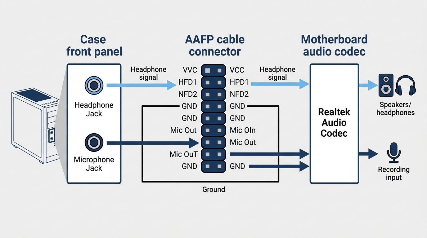
The header carries two audio signals: headphone output and microphone input. When you plug headphones into the front of your case, the signal travels down the case’s internal cable, through the AAFP header, into the onboard audio controller (typically a Realtek codec), and out to your ears. Same process in reverse for the mic.
What AAFP is not: it’s not a USB header, not a power connector, and not the same as the rear I/O audio jacks. People sometimes confuse it with front panel USB headers because they sit near each other on the PCB. They look similar in size but carry entirely different signals. Not interchangeable. At all.
Physically, the AAFP header sits in the lower-right area of most ATX and Micro-ATX motherboards, clustered near the other front panel connectors (F_PANEL, F_USB, etc.). It’s usually a white or black 10-pin housing with one blocked position. You’ll find it labeled in your motherboard’s paper manual and on the PCB silkscreen itself.
AAFP Motherboard Pinout: Every Pin Explained
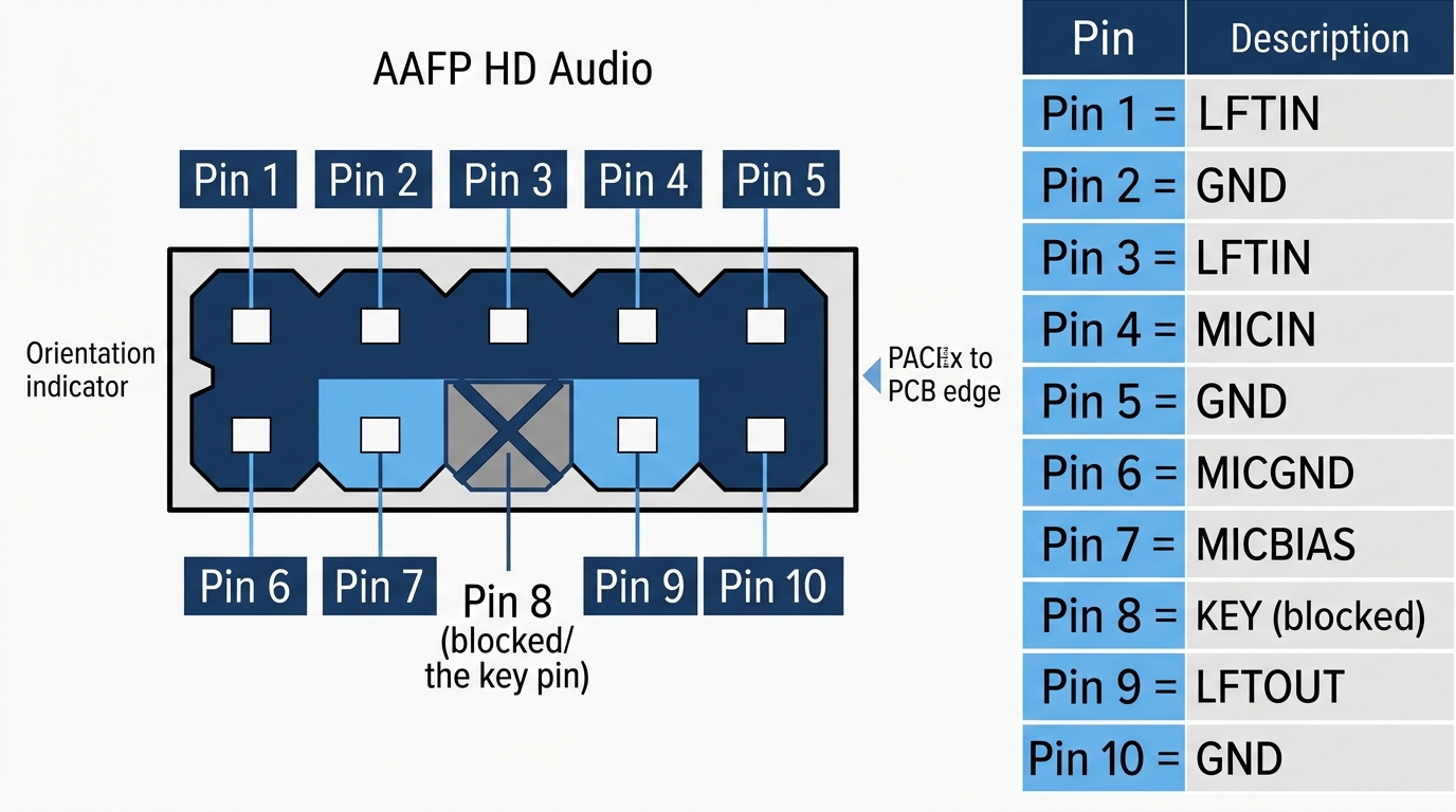
The 10-1 Pin Layout (HD Audio Standard)
The connector uses a 10-pin housing with pin 8 physically blocked. That blocked pin is a key pin, its only job is to prevent you from plugging in the cable backwards or offset. Smart design. You can’t accidentally mis-insert it if you pay attention to the missing pin.
Here’s the full HD Audio pinout:
| Pin | Signal Name | Description |
|---|---|---|
| 1 | MIC2_L | Microphone left channel input |
| 2 | GND | Ground |
| 3 | MIC2_R | Microphone right channel input |
| 4 | -ACZ_DET | Audio codec detect signal |
| 5 | OUT2_R | Headphone right channel (analog audio output) |
| 6 | MIC2_JD | Microphone jack detection |
| 7 | SENSE_SEND | Jack detection sense line from audio codec |
| 8 | (Blocked) | Key pin, no connection, prevents mis-insertion |
| 9 | OUT2_L | Headphone left channel (analog audio output) |
| 10 | LINE2_JD | Line out jack detection |
Physical Characteristics
The connector uses a 2.54mm (0.1 inch) pitch, which is the same standard spacing as most other low-density motherboard headers. The plastic housing is typically white or black depending on the manufacturer, and the case cable usually comes pre-assembled with a single labeled connector block. You won’t need to wire individual pins. Most cases ship the AAFP cable with “HD AUDIO” or “HDA” printed directly on the connector housing.
The keyed housing means there’s only one correct orientation. Line up the notch on the cable connector with the blocked pin position on the header, press firmly, and you’re done.
HD Audio vs. AC’97: What’s the Difference and Which Should You Use?
A Brief History of Front Panel Audio Standards
Two standards have run on the AAFP header over the years. AC’97 (Audio Codec ’97) was Intel’s original spec, introduced in 1997 and widely used through the early 2000s. It was the standard for the Pentium 4 era. Phased out around 2004 when Intel introduced HD Audio (High Definition Audio) as part of the Intel High Definition Audio specification.
The physical AAFP connector can carry either signal. The difference is in how the BIOS configures the audio controller and what the case cable is wired to support. Modern cases all ship with HD Audio cables. If you’re building with a case from 2006 or earlier, double-check which cable type it includes.
HD Audio vs. AC’97: Head-to-Head
| Feature | AC’97 | HD Audio (HDA) |
|---|---|---|
| Max sample rate | 48 kHz | 192 kHz |
| Bit depth | 16-bit | 32-bit |
| Max channels | 6 (5.1 surround) | 8 (7.1 surround) |
| Jack detection | No | Yes |
| Simultaneous front/rear audio | No | Yes |
| Introduced | 1997 | 2004 |
| Status | Deprecated | Current standard |
The quality gap is significant. HD Audio supports 192 kHz / 32-bit audio, four times the sample rate ceiling of AC’97. More practically, jack detection requires HD Audio. That’s the feature that pops up a dialog box when you plug in headphones. No HD Audio, no detection. AC’97 just blindly passes audio whether something is plugged in or not.
How to Switch Between AC’97 and HD Audio in BIOS
On most modern boards the default is already HD Audio. But it’s worth confirming, especially after a fresh Windows install. Go into BIOS (usually Delete or F2 on POST), navigate to Advanced, find Onboard Devices or Onboard Audio Configuration, and look for a setting labeled “Front Panel Audio” or “HD Audio/AC97.” Set it to HD Audio. If you’re uncertain about your specific board, the manual is your first stop. You can find it on your manufacturer’s support page using your exact model number. Always use HD Audio on any build from the last decade.
For Intel’s official HD Audio specification documentation, see the Intel High Definition Audio specification page.
AAFP on Popular Motherboard Brands: Where to Find It and What It’s Labeled
Every major motherboard brand uses the same underlying standard but labels the header differently. This trips up a lot of first-time builders who search the PCB for “AAFP” and can’t find it because they’re on an MSI board. Different name, same function.
ASUS Motherboards
ASUS is the only major brand that actually labels the header “AAFP.” It appears this way across the ROG, TUF Gaming, Prime, and ProArt product lines. Location is consistently the lower-right area of the PCB. The header housing is typically white on ASUS boards. Some higher-end ROG boards label it “HD Audio” instead, same connector, same function. Check the silkscreen near the front panel cluster if you don’t see it immediately.
MSI Motherboards
MSI calls it JAUD1. You’ll find it in the bottom-left corner on most MSI layouts, near the other J-prefixed front panel headers (JCOM, JUSB, etc.). The pinout is identical to the ASUS AAFP. Don’t let the different name confuse you.
Gigabyte and AORUS Motherboards
Gigabyte uses F_AUDIO or HD_AUDIO depending on the board generation. It sits along the bottom edge, usually near the F_PANEL cluster. Older Gigabyte boards may label it “AUDIO” without the F_ prefix.
ASRock Motherboards
ASRock goes with HD_AUDIO1, positioned in the bottom-right area of the PCB. Straightforward labeling, easy to find.
| Manufacturer | Header Label | Standard Used | Typical Location |
|---|---|---|---|
| ASUS | AAFP | HD Audio | Lower-right |
| MSI | JAUD1 | HD Audio | Bottom-left |
| Gigabyte / AORUS | F_AUDIO / HD_AUDIO | HD Audio | Bottom edge |
| ASRock | HD_AUDIO1 | HD Audio | Bottom-right |
| Biostar | F_AUDIO1 | HD Audio | Bottom edge |
For ASUS-specific pinout documentation, the ASUS support portal has downloadable manuals for every current motherboard model, with clearly labeled header diagrams.
How to Connect the AAFP Header: Step-by-Step
What You’ll Need
- Your case’s front panel audio cable (it ships pre-attached to the case interior, bundled with the other front panel cables)
- Your motherboard manual, open to the front panel header diagram page
The cable from the case will have a single connector block labeled “HD AUDIO,” “HDA,” or sometimes “AC’97.” On a modern case, it’s always HD Audio. You don’t need any tools.
Connection Steps
- Open your motherboard manual and locate the AAFP header diagram, it’ll show the exact position on the PCB.
- Find the physical header on the board. Look for a 10-pin housing in the lower section of the PCB, near the F_PANEL cluster. The PCB silkscreen will show the label.
- Pick up the case’s front panel audio cable. Look at the connector, you’ll see one pin hole is filled in or blocked. That matches the key pin (pin 8) on the header.
- Orient the cable connector so the blocked hole aligns with the missing pin on the header.
- Press firmly and evenly until the connector seats flush against the header. No click required, but it should feel snug.
- Boot into Windows and open Sound settings (right-click the speaker icon in the taskbar). Plug headphones into the front jack and confirm the port is detected.
Is the AAFP Header Mandatory?
Nope. Your PC boots and runs normally without it connected. The only consequence: every front-panel 3.5mm port on your case stops working. Your rear I/O audio ports (on the motherboard I/O shield) are completely unaffected. They run directly off the onboard codec regardless of AAFP connection status.
That said, connect it anyway. Takes 10 seconds. Skipping it means plugging into the back of your PC every time you need headphones. Not ideal.
For more on wiring up the full set of front panel connectors, the guide to JFP1 and front panel cable connections covers the power switch, reset, and LED wiring that sits right next to the AAFP header on the PCB.
AAFP Splitter and Adapter: When and Why You’d Need One
What Is an AAFP Splitter?
An AAFP splitter is a Y-cable with one female end (goes to the motherboard header) and two male ends (accept two separate case audio cables). The use case is narrow but real: dual-chamber cases, custom workstation builds, or modified setups where two separate front panel audio assemblies need to share a single motherboard header.
The typical spec is a 9-pin passthrough design, 10cm cable length. You’ll find these for under $10 from cable accessory brands. Just confirm the splitter is rated for HD Audio, not just AC’97 passthrough.
AAFP Extension Cables
Extension cables exist for large tower builds where the case audio cable doesn’t reach. Standard 30cm to 60cm extensions are widely available. Again, confirm HD Audio compatibility before purchasing. Using an AC’97-only extension on a modern build will cause jack detection to fail.
AAFP to USB: Clearing Up the Confusion
A lot of people search for “AAFP to USB adapter” expecting some kind of converter. There isn’t one, because there’s nothing to convert. AAFP carries analog audio signals. USB carries digital data. They’re entirely separate systems. If you want USB audio on your front panel, that’s handled by a completely different header (the F_USB or USB3_GEN1 header). Don’t try to bridge them.
AAFP Not Working: Troubleshooting Guide
No Sound from the Front Panel Headphone Jack
Start with the obvious. Is the AAFP cable actually connected? This is the number one cause. The cable often gets missed during a build because it’s bundled with the other front panel wires and easy to forget. Re-seat it first, then reboot.
If it’s connected and still no audio:
- Check BIOS: confirm Front Panel Audio is set to HD Audio, not AC’97
- Reinstall audio drivers: download the latest Realtek HD Audio driver directly from the Realtek audio codec download page or from your motherboard manufacturer’s support site
- Check the cable type: if you accidentally used an AC’97-labeled cable, switch to the HD Audio one
Front Panel Mic Not Detected
Open Windows Sound settings and go to the Recording tab. Right-click anywhere in the device list and make sure “Show Disabled Devices” is checked. Your front panel mic may be present but disabled. If it’s there, right-click and enable it.
Some boards also have a “Front Panel Mic Mute” setting buried in BIOS under Advanced audio options. Check that too. If neither fixes it, re-seat the AAFP connector, a slightly off-angle connection causes intermittent signal issues on the mic pins specifically.
Jack Detection Not Working
Plugging in headphones does nothing? No dialog box, no auto-switch? That’s almost always AC’97 mode selected in BIOS. Jack detection is exclusively an HD Audio feature. Switch the BIOS setting to HD Audio and reinstall your audio drivers. Clean driver reinstall (uninstall first, reboot, then install fresh) resolves this about 90% of the time.
Quick Troubleshooting Checklist
- 🟢 AAFP cable is fully seated and correctly oriented
- 🟢 BIOS Front Panel Audio setting is set to HD Audio
- 🟢 Realtek (or vendor) audio drivers are current
- 🟢 Front panel ports are enabled and not disabled in Windows Sound settings
- 🟡 Tested rear panel audio to confirm onboard codec is functioning
- 🟡 Confirmed case cable is labeled “HD Audio” not “AC’97”
AAFP vs. Other Front Panel Headers: Don’t Mix Them Up
The AAFP header lives in a cluster of similarly sized connectors at the bottom of the PCB. They look alike. Plugging the wrong cable into the wrong header won’t fry anything (they’re keyed to prevent most mistakes), but it will definitely leave you confused about why nothing works.
| Header | Full Name | Function | Pin Count |
|---|---|---|---|
| AAFP | Analog Audio Front Panel | Front audio jacks (headphone + mic) | 10-1 pin |
| F_PANEL | Front Panel | Power button, reset, HDD LED, power LED | 9-1 pin |
| F_USB / USB2 | Front Panel USB 2.0 | USB 2.0 front ports | 9-1 pin |
| USB3_GEN1 | Front Panel USB 3.0 | USB 3.0 front ports | 19-1 pin |
| USB3_GEN2 | Front Panel USB 3.2 Gen 2 | High-speed USB front port | 20-pin |
| THUNDERBOLT | Thunderbolt Header | Thunderbolt front port (high-end boards only) | 5-pin or 14-1 pin (varies by generation) |
The AAFP and F_PANEL headers are the two most commonly swapped by accident because they’re both 9-10 pin and often sit adjacent. They’re keyed differently, so forced insertion is difficult, but double-checking before you push anything in is always worth it. If you’re sorting out the differences between front panel USB 2.0 and USB 3.0 headers, the speed and bandwidth differences matter more than most builders realize for front-panel transfer speeds.
Frequently Asked Questions
What is the AAFP on a motherboard?
AAFP stands for Analog Audio Front Panel. It’s the 10-pin (9+1) header on a motherboard that connects your PC case’s front 3.5mm headphone and microphone jacks to the onboard audio controller. Without it connected, those front-panel ports produce no audio.
Is HD Audio and AAFP the same thing?
Not exactly. AAFP is the physical connector, the header on the motherboard. HD Audio (High Definition Audio) is the signal standard carried over that connector. The same AAFP header also supports the older AC’97 standard, but HD Audio is the current and recommended setting for any modern build. Think of AAFP as the road and HD Audio as what drives on it.
What does AAFP stand for in computers?
AAFP stands for Analog Audio Front Panel. The term is primarily used by ASUS on their motherboard PCBs and documentation. Other manufacturers use different label names (JAUD1, F_AUDIO, HD_AUDIO1) for the exact same header.
Is AAFP the front panel?
AAFP is one part of the front panel header cluster, not the entire front panel. “Front panel” collectively refers to all the connectors along the bottom edge of the motherboard, power switch, reset, LEDs, USB ports, and audio. AAFP handles audio specifically. The main power and reset connections go to the separate F_PANEL header.
Do I need to connect the AAFP header?
You don’t need it to boot or run your PC. It’s not required for system operation. But if you want to use the headphone or microphone jacks on the front of your case, yes, AAFP must be connected. Your rear I/O audio ports work independently and are unaffected either way.
The Short Version
AAFP is Analog Audio Front Panel, a 10-1 pin keyed header that bridges your case’s front audio jacks to the motherboard’s onboard audio controller. It uses a 2.54mm pitch connector, supports HD Audio (recommended) and legacy AC’97, and sits in the lower-right PCB area on most boards. ASUS labels it AAFP; MSI calls it JAUD1; Gigabyte uses F_AUDIO; ASRock goes with HD_AUDIO1. All the same thing. It’s not required to boot, but skip it and your front-panel headphone and mic ports do nothing. Connect it, set BIOS to HD Audio, and you’re done. Takes ten seconds.

Alex has been building and tweaking custom PCs for over 12 years. From budget builds to full custom water loops, he’s assembled more than 50 systems and helped hundreds of builders troubleshoot their rigs. When he’s not benchmarking the latest hardware, you’ll find him optimizing airflow setups or stress-testing overclocks.