JFP1 on Motherboard: What It Is and How to Connect Front Panel Cables
JFP1 on a motherboard stands for Jumper Front Panel 1, a 9-pin or 10-pin header that connects case power buttons, reset buttons, and indicator LEDs to the motherboard.
Last updated: September 2026
Table of Contents
- What Is JFP1 on a Motherboard?
- JFP1 Definition and Full Name
- What Does JFP1 Actually Do?
- JFP1 Pin Layout and Pinout Explained
- Standard JFP1 Pinout (9-1 Layout)
- Does Polarity Matter on JFP1?
- JFP1 Pinouts by Motherboard Brand (MSI, ASUS, Gigabyte, ASRock)
- The MSI JFP1 Header Specifically
- ASUS Q-Connector Shortcut
- What Is JFP2 and How Is It Different from JFP1?
- JFP2 Definition
- Do You Need to Connect JFP2?
- How to Connect Front Panel Cables to JFP1 (Step-by-Step)
- What You Need Before You Start
- Identifying Your Case Front Panel Cables
- Step-by-Step JFP1 Connection Process
- What If Your Cables Don’t Reach JFP1?
- JFP1 Troubleshooting: When Things Go Wrong
- PC Won’t Turn On After Connecting JFP1
- Power LED Not Lighting Up
- HDD LED Never Blinks
- Reset Button Triggers Power-Off Instead of Restart
- Can You Start a PC Without Connecting JFP1?
- Frequently Asked Questions About JFP1
- What does JFP1 stand for?
- What is JFP1 and JFP2?
- Is JFP1 for the power button?
- What happens if I connect JFP1 cables in the wrong order?
- Where is JFP1 located on the motherboard?
- The Bottom Line
If your PC won’t turn on after a fresh build, there’s a good chance JFP1 is the culprit. What is JFP1 on a motherboard? It’s the primary communication bridge between your case’s physical controls and the motherboard’s logic. What does JFP1 mean on a motherboard, practically speaking? It means that without it, pressing your power button does absolutely nothing. This guide covers the full pinout, step-by-step connection process, brand-specific differences between MSI, ASUS, Gigabyte, and ASRock, and a troubleshooting section for when things go sideways.
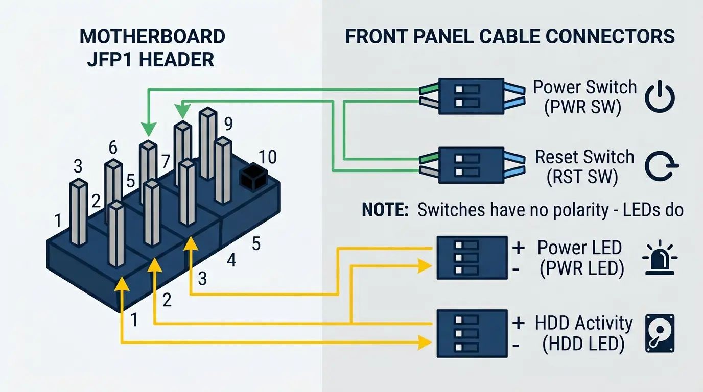
- 🟢 Power Switch (PWR SW), pins 6 & 8, no polarity concern
- 🟢 Reset Switch (RST SW), pins 5 & 7, no polarity concern
- 🟡 Power LED, pins 2 (+) & 4 (−), polarity matters (but won’t damage anything if reversed)
- 🟡 HDD LED, pins 1 (+) & 3 (−), polarity matters (same as above)
- 🔴 Pin 10: no pin, it’s the orientation key. Pin 9: leave it empty (reserved on MSI JFP1)
- 🟢 JFP2 (MSI), separate header for the case speaker, not required to boot
- 👉 Interactive pinout for MSI, ASRock, ASUS and Gigabyte
What Is JFP1 on a Motherboard?
JFP1 Definition and Full Name
JFP1 stands for Jumper Front Panel 1. The “jumper” part is legacy naming from early PC design, where connecting (or “jumping”) two pins would complete a circuit. It stuck even though modern front panel headers are far more than simple jumper blocks. The “1” just means it’s the primary front panel header, distinguishing it from the secondary JFP2.
On nearly every ATX and mATX motherboard, you’ll find JFP1 in the bottom-right corner of the PCB, close to the board’s edge. That placement isn’t random. It puts the header as close as possible to where your case’s front panel cable bundle exits the chassis, keeping cable runs short and clean. On Mini-ITX boards, placement varies more, so always check your manual. That’s exactly why reading your specific board’s manual matters, not just a generic pinout diagram you find online.
What Does JFP1 Actually Do?
JFP1 handles four front panel functions:
- Power button (PWR SW), sends the on/off signal when you press the case power button
- Reset button (RST SW), triggers a hard restart without cutting power entirely
- HDD activity LED, flickers when your storage drive is actively reading or writing data
- Power LED, stays solid when the PC is on, pulses during sleep on boards that support it
Without JFP1 connected, the power button on your case is inert. The motherboard never receives the power-on signal. Dead button. This is probably the single most common reason a first-time builder’s PC appears completely dead on first boot.
One thing worth knowing: the motherboard has onboard pull-up resistors already built into the JFP1 header. You don’t need to add any external resistors to make switches or LEDs work. Just connect the cables directly. Simple.
JFP1 Pin Layout and Pinout Explained

Standard JFP1 Pinout (9-1 Layout)
Most JFP1 headers use a 2×5 pin arrangement with one pin intentionally absent, giving you 9 usable pins in a 10-pin block. That missing pin is the “key”, it physically prevents you from plugging in a connector in the wrong orientation. MSI’s manuals use this layout, and it follows Intel’s front panel header reference:
| Pin Number | Signal | Description |
|---|---|---|
| 1 | HDD LED + | Hard drive activity LED positive |
| 2 | Power LED + | Power indicator LED positive |
| 3 | HDD LED − | Hard drive activity LED negative/ground |
| 4 | Power LED − | Power indicator LED negative/ground |
| 5 | Reset Switch | Reset button, ground side |
| 6 | Power Switch | Power button, signal side |
| 7 | Reset Switch | Reset button, signal side |
| 8 | Power Switch | Power button, ground side |
| 9 | Reserved | Leave empty. MSI marks it reserved; on Intel’s reference it carries +5V and on ASRock it is ground |
| 10 | No pin | Missing on purpose: this is the orientation key |
Sources: Intel’s front panel header pinout and the JFP1 page of MSI’s PRO X670-P WiFi manual. The switches aren’t polarity-sensitive, so the ground and signal sides only matter when you bridge pins by hand.
Does Polarity Matter on JFP1?
It depends on the connector. Here’s the breakdown:
- Power Switch and Reset Switch: Polarity doesn’t matter. These are simple momentary contact switches. They complete a circuit when pressed, regardless of which wire is positive or negative. Connect them either way.
- HDD LED and Power LED: Polarity technically matters. LEDs are diodes, they only conduct current in one direction. If you reverse them, the LED simply won’t light. No damage occurs, nothing burns out. Just a dark LED.
Quick fix if your power LED is dark after a build: pull the connector off, flip it 180 degrees, and reseat it. That’s almost always the fix. Worth trying before you start tracing wiring problems elsewhere.
JFP1 Pinouts by Motherboard Brand (MSI, ASUS, Gigabyte, ASRock)

Pins 1 to 8 are laid out the same way on all four major brands. What differs is pin 9, the size of the header, and where the speaker and a 3-pin power LED plug go. Here’s what each manufacturer’s manual shows:
| Brand | Header Label | Layout | What’s Different | Checked Against |
|---|---|---|---|---|
| MSI | JFP1 | 9-pin (2×5, pin 10 missing) | Pin 9 reserved. The speaker goes on a separate 4-pin JFP2 header. | MSI PRO X670-P WiFi manual |
| ASRock | PANEL1 | 9-pin (2×5, pin 10 missing) | Pin 9 is ground. The speaker and a 3-pin power LED plug go on a separate 7-pin SPK_PLED1 header. | ASRock X570 Phantom Gaming 4 guide |
| ASUS | PANEL (System Panel) | 20-3 pin | Pins 1 to 8 standard. Adds a 4-pin speaker section and a 3-pin power LED position (pins 11 and 15). | ROG Strix B550-F Gaming WiFi II manual |
| Gigabyte | F_PANEL | 20-3 pin | Pins 1 to 8 standard. Chassis intrusion on pins 9 and 11, speaker on 14 and 20, 3-pin power LED on 15 to 19. | Gigabyte B760 DS3H manual |
Interactive front panel pinout
Pick your board brand, then tap a cable to see exactly which pins it goes on. Pin 1 is bottom left (▶); the top row holds the even pins.
MSI JFP1 (9-pin)
Pin 9 is reserved: leave it empty. The case speaker goes on the separate JFP2 header, not on JFP1.
Full pin list for MSI JFP1
| Pin | Function |
|---|---|
| 1 | HDD LED + |
| 2 | Power LED + |
| 3 | HDD LED - |
| 4 | Power LED - |
| 5 | Reset (ground) |
| 6 | Power switch |
| 7 | Reset switch |
| 8 | Power (ground) |
| 9 | Reserved |
| 10 | No pin |
ASRock PANEL1 (9-pin)
Pin 9 is ground: leave it empty. The speaker and a 3-pin power LED plug go on the separate SPK_PLED1 header.
Full pin list for ASRock PANEL1
| Pin | Function |
|---|---|
| 1 | HDD LED + |
| 2 | Power LED + |
| 3 | HDD LED - |
| 4 | Power LED - |
| 5 | Reset (ground) |
| 6 | Power switch |
| 7 | Reset switch |
| 8 | Power (ground) |
| 9 | Ground |
| 10 | No pin |
ASUS PANEL (20-3 pin)
Based on the ROG Strix B550-F Gaming WiFi II manual. The first four columns match the standard 9-pin layout.
Full pin list for ASUS PANEL
| Pin | Function |
|---|---|
| 1 | HDD LED + |
| 2 | Power LED + |
| 3 | HDD LED - |
| 4 | Power LED - |
| 5 | Reset (ground) |
| 6 | Power button |
| 7 | Reset switch |
| 8 | Power (ground) |
| 9 | Not connected |
| 10 | Not used |
| 11 | Power LED + (3-pin) |
| 12 | Speaker +5V |
| 13 | Not used |
| 14 | Speaker ground |
| 15 | Power LED - (3-pin) |
| 16 | Speaker ground |
| 17 | Not used |
| 18 | Speaker |
| 19 | Not used |
| 20 | Not used |
Gigabyte F_PANEL (20-3 pin)
Based on the B760 DS3H manual. The first four columns match the standard 9-pin layout; pin 9 is chassis intrusion here, not reserved.
Full pin list for Gigabyte F_PANEL
| Pin | Function |
|---|---|
| 1 | HDD LED + |
| 2 | Power LED + |
| 3 | HDD LED - |
| 4 | Power LED - |
| 5 | Reset - |
| 6 | Power + |
| 7 | Reset + |
| 8 | Power - |
| 9 | Chassis intrusion - |
| 10 | No pin |
| 11 | Chassis intrusion + |
| 12 | No pin |
| 13 | No pin |
| 14 | Speaker + |
| 15 | Power LED + |
| 16 | Not connected |
| 17 | Power LED - |
| 18 | Not connected |
| 19 | Power LED - |
| 20 | Speaker - |
Layouts come from the manufacturers' manuals. Boards differ, so always confirm against the manual for your exact model.
The MSI JFP1 Header Specifically
MSI is by far the most commonly searched brand when it comes to JFP1 questions, and for good reason. MSI explicitly labels the header “JFP1” on the PCB silkscreen, matching the terminology in their manual exactly. That naming consistency makes it easier to find than on ASUS (PANEL) or Gigabyte (F_PANEL) boards.
On MSI boards like the MAG B550 Tomahawk and MAG Z690 series, MSI uses a secondary header called JFP2 specifically for the internal PC speaker/buzzer. These two headers are separate. Don’t try to plug your speaker into JFP1, it won’t fit correctly, and even if it did, it’s the wrong header.
ASUS Q-Connector Shortcut
ASUS includes a Q-Connector adapter on most ROG and TUF series boards. It’s a small plastic block that lets you connect all your front panel cables to the adapter while it’s in your hand outside the case, then plug the whole assembled block into F_PANEL in one motion. If you’ve ever tried to seat individual 2-pin connectors onto a header buried in a dark corner of a mid-tower, you understand why this matters. Genuinely useful. Gigabyte ships a similar adapter, the G-Connector, with many of its boards, for example the X870 Aorus Elite WiFi7.
What Is JFP2 and How Is It Different from JFP1?
JFP2 Definition
JFP2 is MSI’s secondary front panel header: a 4-pin header for the case speaker and buzzer that produce POST beep codes. MSI’s manuals list the pins as Speaker -, Buzzer +, Buzzer – and Speaker +. Other brands handle the speaker differently: ASUS and Gigabyte put the speaker pins on the main panel header, and ASRock uses a separate SPK_PLED1 header.
Here’s how the two headers stack up side by side:
| Feature | JFP1 | JFP2 |
|---|---|---|
| Purpose | Power/Reset buttons + LEDs | PC speaker / POST beep buzzer |
| Pin count | 9 pins (10-pin block with key) | 4 pins |
| Required for boot? | Yes (power button won’t work without it) | No, optional but useful |
| Polarity sensitive? | LEDs only | Yes (speaker has +/−) |
| Present on all boards? | Yes (called PANEL, F_PANEL or PANEL1 on other brands) | MSI boards; other brands put the speaker elsewhere |
Do You Need to Connect JFP2?
Not required for normal operation. Your PC will boot without it. That said, connecting the speaker is highly recommended during any new build. POST beep codes are the fastest diagnostic tool you have when a fresh build refuses to start. One beep usually means all clear. Multiple beeps in a pattern point to specific failures, RAM not seated, GPU not detected, and so on. Skip the speaker and you’re troubleshooting blind.
If your case didn’t include an internal speaker, they’re cheap (usually under $3) and available from any PC parts retailer. Worth having on hand for any build.
How to Connect Front Panel Cables to JFP1 (Step-by-Step)

What You Need Before You Start
- Your motherboard manual, download the PDF from the manufacturer’s support page if you’ve lost the physical copy
- Your case’s front panel cable bundle (typically 5 to 8 individual connectors)
- A flashlight or phone torch, headers near the bottom of the board in a closed case are dark
- Long-nose tweezers (optional but genuinely helpful in tight spaces)
Identifying Your Case Front Panel Cables
Most modern cases include the following front panel cables:
- PWR SW (Power Switch), 2-pin, usually white or red/black
- RST SW or RESET (Reset Switch), 2-pin, usually white or blue/black
- PWR LED+ and PWR LED− (Power LED), may arrive as two separate 1-pin connectors or a pre-joined 3-pin
- HDD LED (Hard Drive Activity LED), 2-pin, polarity marked with + and − printed on the connector housing
Some cases supply the Power LED as a 3-pin plug with an empty middle hole. It fits the 3-pin power LED position on ASUS (pins 11 and 15) and Gigabyte (pins 15 to 19) headers, or ASRock’s separate SPK_PLED1 header. MSI’s JFP1 only has the 2-pin position (pins 2 and 4), so there you need separate 1-pin or 2-pin leads.
Step-by-Step JFP1 Connection Process
- Locate JFP1 on your motherboard. It’s usually in the bottom-right area, labeled JFP1 on MSI, PANEL on ASUS, F_PANEL on Gigabyte and PANEL1 on ASRock.
- Open your motherboard manual to the JFP1 diagram. Confirm the pin layout for your specific board, don’t assume it matches a generic diagram.
- Find the key pin (the missing pin, position 10 in the 2×5 block) to orient yourself. This is your anchor point.
- Connect Power Switch (PWR SW) to pins 6 and 8. Polarity doesn’t matter.
- Connect Reset Switch (RST SW) to pins 5 and 7. Polarity doesn’t matter.
- Connect HDD LED to pins 1 (+) and 3 (−). Match polarity, (+) wire to pin 1.
- Connect Power LED to pins 2 (+) and 4 (−). Match polarity, (+) wire to pin 2.
- Test before closing the case. Press the power button. If the board POSTs, all connections are correct. Don’t button up the case until you’ve confirmed this works.
What If Your Cables Don’t Reach JFP1?
Real problem in full-tower cases paired with mATX boards. The header sits near the board’s bottom edge, but if the board is mounted higher in a large case, the front panel cables can come up short. The fix: front panel extension cables, which are widely available for a few dollars. Also check whether you’ve been routing cables behind the motherboard tray unnecessarily, that can eat several inches of cable length you didn’t need to lose.
JFP1 Troubleshooting: When Things Go Wrong
PC Won’t Turn On After Connecting JFP1
Most likely cause: the Power Switch connector is on the wrong pins. Check pins 6 and 8 specifically, that’s the PWR SW pair on nearly every standard JFP1 layout. Also confirm the connector is fully seated. It’s easy to get a connector only one pin deep where it feels seated but isn’t making contact.
If you’ve double-checked the pin placement and still nothing: use a flathead screwdriver to briefly bridge pins 6 and 8 directly on the header. If the PC starts, the cable connection is the problem, either the connector is faulty or the cable from the case is broken. If the PC still doesn’t start, the issue is elsewhere (PSU, RAM, or a different board problem).
While you’re in troubleshooting mode, checking for a white light on your motherboard can help identify whether the problem is GPU initialization versus a front panel issue entirely.
Power LED Not Lighting Up
Almost always a polarity reversal. Pull the PWR LED connector off, flip it 180 degrees, and reseat. That fixes it 90% of the time.
If the LED is still dark after flipping: test the LED itself using a 3V coin cell battery. Touch the + side of the battery to the (+) wire and the − side to the (−) wire. If the LED lights from the battery, the LED is fine and you have a wiring issue at the header. If it doesn’t light, the LED in your case is dead.
One edge case: some older cases use a dual-color PWR/SLP LED (green for on, amber for sleep) that needs a 3-pin connection to show both states. If you only have a standard 2-pin power LED port on the motherboard, you’ll only see the “on” state and that’s expected behavior.
HDD LED Never Blinks
If your primary drive is an NVMe SSD, this is probably normal. NVMe drives don’t always trigger the HDD LED signal the way SATA drives do. The activity indicator was designed around traditional spinning disks and SATA SSDs. On many NVMe-primary systems, the LED barely flickers or stays dark entirely. Not a defect.
If you’re running a SATA drive and the LED is dead: check polarity first, then check BIOS settings.
Reset Button Triggers Power-Off Instead of Restart
Classic swap mistake. The PWR SW and RST SW connectors are on the wrong pins. Pull both off and switch their positions. Problem solved.
| Symptom | Most Likely Cause | Fix |
|---|---|---|
| PC won’t turn on | PWR SW on wrong pins | Move connector to pins 6 & 8 |
| Power LED stays dark | Reversed polarity | Flip LED connector 180° |
| HDD LED never blinks | NVMe drive (expected) or reversed polarity | Normal on NVMe / flip connector if SATA |
| Reset causes shutdown | PWR SW and RST SW swapped | Swap the two connectors |
| Intermittent power button | Connector not fully seated | Push in firmly until secure |
Can You Start a PC Without Connecting JFP1?
Yes, technically. Briefly bridging the two power switch pins (pins 6 and 8) with a conductive object, a flathead screwdriver works perfectly, will trigger the power-on signal exactly the same way your case button does. This is called bench testing, and it’s a legitimate diagnostic technique used to test a build on an open bench before the board is installed in the case.
You can’t use this as a long-term replacement for proper wiring. It’s a one-time diagnostic shortcut, not a daily driver solution. Also: bridging the wrong pins is rarely catastrophic, but bridging the reset pins instead of the power pins will trigger a restart instead of a boot, which is just annoying rather than dangerous. Bridge carefully and count your pins before touching anything.
Frequently Asked Questions About JFP1
What does JFP1 stand for?
JFP1 stands for Jumper Front Panel 1. “Jumper” refers to the electrical bridging function inherited from early PC design conventions. “Front panel” describes the header’s purpose, connecting physical case controls to the motherboard. The “1” identifies it as the primary front panel header, separate from the secondary JFP2 header found on most full-size boards.
What is JFP1 and JFP2?
JFP1 is the primary front panel header handling the power button, reset button, power LED, and HDD activity LED. JFP2 is a secondary header used primarily for the internal PC speaker that produces POST beep codes during startup diagnostics. JFP1 is required for your power button to function. JFP2 is optional for normal operation but genuinely useful when diagnosing a new build that won’t boot.
Is JFP1 for the power button?
Partly. The power button connects to JFP1 (specifically pins 6 and 8 on the standard layout), but JFP1 handles more than just the power button. It’s also the connection point for the reset button, the power LED, and the HDD activity LED. All four front panel functions run through the same 9-pin block.
What happens if I connect JFP1 cables in the wrong order?
For switch connectors (power and reset), nothing bad happens, they’re polarity-independent and will still function correctly regardless of which direction you plug them in. For LED connectors (power LED and HDD LED), reversing polarity means the LED won’t light, but no hardware damage occurs. No connection on JFP1 will damage your motherboard or case components if wired incorrectly. The worst outcome is a dark LED or a non-functional button that you fix by reseating the connector.
Where is JFP1 located on the motherboard?
On ATX and mATX boards, JFP1 is almost always in the bottom-right section of the PCB, near the board’s edge. The label is printed directly in the PCB silkscreen next to the header pins. On Mini-ITX boards, space constraints push headers into less predictable positions, so always verify in your manual before searching by eye. If you’re struggling to find it, search your board model’s name plus “manual” for a free PDF with a full component diagram.
The Bottom Line
JFP1 is one of the last things you connect in a build and one of the first things that causes confusion. Here’s what to keep in mind:
- JFP1 = Jumper Front Panel 1, your board’s primary front panel header
- Controls: power button, reset button, power LED, HDD activity LED
- Standard layout: 9 pins in a 10-pin block, with pin 10 absent as an orientation key and pin 9 reserved (do not use)
- Switches are not polarity-sensitive. LEDs are, but reversed polarity only kills the light, not the hardware.
- MSI calls it JFP1, ASUS calls it PANEL, Gigabyte F_PANEL and ASRock PANEL1. Pins 1 to 8 match on all of them
- JFP2 is a separate header for the PC speaker, useful for POST diagnostics, not required for boot
- If something doesn’t work: check polarity first, then check which pins you’re on
If you’re digging into other motherboard headers and connectors, understanding how RGB headers work and how to connect them is a natural next step for getting your build fully wired. Your case’s headphone and mic jacks use a header of their own, so if they stay silent, see what the AAFP header is and how to connect it.
Check your manual, take it one connector at a time, and test before you close the case. That one habit saves hours of troubleshooting.

Alex has been building and tweaking custom PCs for over 12 years. From budget builds to full custom water loops, he’s assembled more than 50 systems and helped hundreds of builders troubleshoot their rigs. When he’s not benchmarking the latest hardware, you’ll find him optimizing airflow setups or stress-testing overclocks.