USB 2.0 vs 3.0 vs 3.2 Headers: The Differences
A USB 2.0 header is a 9-pin internal motherboard connector linking front-panel USB ports to the board, supporting 480 Mbps and 500 mA.
Last updated: October 2026
Table of Contents
- Quick Answer: What Is a USB 2.0 Header?
- What Is a USB Header? (Quick Primer)
- Internal vs. External USB, What’s the Difference?
- USB 2.0 Header, Full Breakdown
- Physical Description and Pin Layout
- USB 2.0 Header Specs at a Glance
- Where You’ll Find USB 2.0 Headers in 2026
- USB 3.0 Header (USB 3.2 Gen 1), Full Breakdown
- Physical Description and Pin Layout
- USB 3.0 19-Pin Header Pinout
- USB 3.0 / 3.2 Gen 1 Header Specs at a Glance
- Common Use Cases
- USB 3.2 Gen 2 and Gen 2×2 Headers, The Fastest Internal Connectors
- USB 3.2 Gen 2 Header (10 Gbps)
- USB 3.2 Gen 2×2 Header (20 Gbps), Type-C Exclusive
- USB Header Comparison Table, All Generations Side by Side
- Can You Plug USB 2.0 Into a 3.0 Header (And Vice Versa)?
- What to Do If Your Motherboard Has No USB 2.0 Header
- USB 2.0 Header Splitters and Hubs, Expanding Limited Headers
- What Is a USB 2.0 Header Splitter?
- What Is a USB 2.0 Internal Header Hub?
- Practical Tips: Connecting USB Headers During a PC Build
- Identifying Your Headers Before You Build
- Common Wiring Mistakes (And How to Avoid Them)
- Does It Matter Which USB Header You Use?
- FAQ, USB Header Questions Answered
- What is a USB 2.0 internal header?
- Can you plug USB 2.0 into a 3.0 header?
- What is the difference between a USB 3 header and a USB 2 header?
- Does it matter which USB header you plug your case cables into?
- What do I do if my motherboard has no USB 2.0 header?
- Final Thoughts
Quick Answer: What Is a USB 2.0 Header?
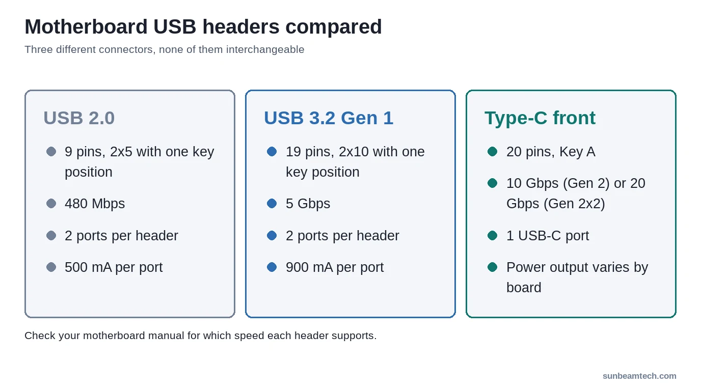
A USB 2.0 header is the internal 9-pin (2×5) connector on your motherboard that your case’s front-panel USB cables plug into. It carries data and power to the external USB-A ports on the front of your case. The USB 3.0 header does the same job but uses a larger 19-pin connector and delivers 5 Gbps instead of 480 Mbps. Front-panel USB-C ports use a third connector: a compact 20-pin Type-C header, at 10 Gbps for USB 3.2 Gen 2 or 20 Gbps for Gen 2×2.
9-pin. 19-pin. 20-pin Type-C. Three different connectors, none of them physically interchangeable. Here’s everything you need to know before you route a single cable.
- 🟢 USB 2.0 header (9-pin): 480 Mbps, 500 mA, fine for Bluetooth dongles, RGB controllers, card readers
- 🟢 USB 3.0 / 3.2 Gen 1 header (19-pin): 5 Gbps, 900 mA, use this for fast front-panel ports
- 🟡 USB 3.2 Gen 2 Type-C header (20-pin): 10 Gbps, one front USB-C port, mid-to-high-end boards
- 🟡 USB 3.2 Gen 2×2 Type-C header (20-pin): 20 Gbps, one front USB-C port, premium boards
- 🔴 Mixing headers: USB 2.0 and USB 3.0 cables are physically incompatible at the header level, an adapter is required
What Is a USB Header? (Quick Primer)
USB headers are internal connectors. Not the ports on the back of your PC, not the slots on your monitor hub. These live on the motherboard PCB itself and are never directly touched by an external device. Instead, they connect via a ribbon or multi-wire cable to the external USB ports built into your case’s front panel.
Internal vs. External USB, What’s the Difference?
The signal path works like this: a device plugs into the external USB-A (or USB-C) port on your case front, that port is wired internally to a cable, and that cable terminates in a header connector that clips onto the motherboard pins. The header itself carries both the data lines and the 5V power rail.
All three header generations serve the same purpose. The differences are speed, power delivery, pin count, and physical size. A USB 2.0 front-panel port and a USB 3.2 front-panel port look nearly identical from the outside. Inside your case, though, the cables and motherboard connectors are completely different.
According to Lenovo’s technical documentation on USB headers, a USB 2.0 header offers maximum transfer speeds of up to 480 Mbps while a USB 3.0 header provides speeds up to 5 Gbps, a tenfold jump from the same-looking front panel.
USB 2.0 Header, Full Breakdown
The USB 2.0 header has been on motherboards since the early 2000s and it’s still on virtually every board shipping today. It’s the smallest of the three header types and the easiest to identify once you know what you’re looking for.
Physical Description and Pin Layout
The standard USB 2.0 header uses a 2×5 pin arrangement, 10 pin positions total, with one pin physically blocked (the key pin) to prevent incorrect orientation. That leaves 9 usable positions, of which 8 are active signal pins. One header supports two USB 2.0 ports simultaneously.
| Pin | Signal | Wire Color (Standard) |
|---|---|---|
| 1 | VCC (+5V) | Red |
| 2 | VCC (+5V) | Red |
| 3 | Data – (D−) | White |
| 4 | Data – (D−) | White |
| 5 | Data + (D+) | Green |
| 6 | Data + (D+) | Green |
| 7 | GND | Black |
| 8 | GND | Black |
| 9 | Key (blocked) | , |
| 10 | S-GND (optional) | Black (thicker) |
Two header variants exist: the 2×5 (10-position) layout shown above, which includes the S-GND pin, and the 2×4 (8-position) layout, which omits it. If your cable has an S-GND wire and your header doesn’t have a matching pin, leave it floating. Totally safe. The S-GND wire is noticeably thicker than the others, you’ll recognize it immediately.
You’ll also occasionally see a pin labeled “NC” (No Connection) on some headers. That’s just an empty pin with no electrical function. You can connect the S-GND wire there without any issue.
USB 2.0 Header Specs at a Glance
- Max data transfer rate: 480 Mbps (High-Speed USB)
- Power delivery per port: 500 mA / 2.5W
- Voltage: 5V
- Backward compatibility: USB 1.1 (1.5 Mbps Low-Speed, 12 Mbps Full-Speed)
- Ports per header: 2
Where You’ll Find USB 2.0 Headers in 2026
Still everywhere. Even high-end Z890 and X870E boards ship with one or two USB 2.0 headers. They’re not going away because there’s genuine demand for them. Internal Bluetooth receivers, AIO cooler USB connections, RGB lighting controllers, internal card readers, none of these need 5 Gbps throughput, and they all draw well under 500 mA. Burning a USB 3.0 header on an RGB controller is wasteful. USB 2.0 is the right tool for those jobs.
One caution: a single USB 2.0 header is hardware-limited to two active devices simultaneously, regardless of manufacturer. Splitting the header doesn’t multiply that, it stays at two. Plan your internal USB budget accordingly.
USB 3.0 Header (USB 3.2 Gen 1), Full Breakdown
USB 3.0 has been through a naming overhaul. What was once “USB 3.0” became “USB 3.1 Gen 1” and is now officially called USB 3.2 Gen 1. Same hardware, different label. If your motherboard manual says any of those three names for a header, they all refer to the same 5 Gbps connector.
Physical Description and Pin Layout
The USB 3.0 header is the big one: 19 pins in a 2×10 layout, with the twentieth position left empty as the key. It’s usually blue, though color isn’t a reliable guide on every board.
One full 19-pin header block supports two front-panel USB 3.0 ports. Each port gets its own set of SuperSpeed data lanes (TX+, TX-, RX+, RX-) in addition to the standard D+ and D- lines carried over from USB 2.0 for backward compatibility.
USB 3.0 19-Pin Header Pinout
Intel’s USB 3.0 internal connector specification defines the pins. Each of the two ports gets its own SuperSpeed receive and transmit pairs plus a USB 2.0 D+/D- pair, and the two ports share power and ground:
| Pins | Port 1 | Port 2 |
|---|---|---|
| SuperSpeed receive (RX-, RX+) | 2, 3 | 18, 17 |
| SuperSpeed transmit (TX-, TX+) | 5, 6 | 15, 14 |
| USB 2.0 (D-, D+) | 8, 9 | 12, 11 |
| Power (Vbus) | 1 | 19 |
| Ground | 4, 7 | 13, 16 |
| ID (over current protection) | 10 (shared) | |
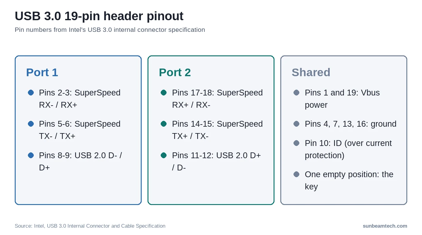
The USB 2.0 pair on each port is why a USB 3.0 front-panel cable still works, at 480 Mbps, through a 19-pin to 9-pin adapter: the adapter only passes those pins through.
USB 3.0 / 3.2 Gen 1 Header Specs at a Glance
- Max data transfer rate: 5 Gbps (SuperSpeed)
- Power delivery per port: 900 mA / 4.5W
- Voltage: 5V
- Raw throughput vs. USB 2.0: approximately 10× faster
- Backward compatibility: USB 2.0, USB 1.1
- Ports per header: 2
Common Use Cases
Front-panel SuperSpeed ports on mid-tower and full-tower cases are the primary application. If your case ships with a fat, blue-coded internal USB cable, that’s your USB 3.0 header cable. Use it on a USB 3.0 header, don’t adapt it down to USB 2.0 unless you have no other option.
Fast external SSDs, USB flash drives rated for SuperSpeed, and game controllers with rumble (which pull more current) all benefit from a USB 3.0 header connection. The extra 400 mA per port over USB 2.0 headers matters more than most people realize for USB-powered hard drives and high-current peripherals.
For a deeper look at how USB generation differences affect real-world transfer speeds at the external port level, the guide on USB 2.0 vs 3.0 speed differences covers practical benchmarks in detail.
USB 3.2 Gen 2 and Gen 2×2 Headers, The Fastest Internal Connectors
“USB 3.2” alone is a marketing umbrella term. Meaningless without the generation suffix. Always look for Gen 1, Gen 2, or Gen 2×2 in the spec sheet.
USB 3.2 Gen 2 Header (10 Gbps)
USB 3.2 Gen 2 doubles the lane speed of Gen 1 from 5 Gbps to 10 Gbps. On current boards, the Gen 2 front-panel header is normally the compact Type-C connector rather than the 19-pin block: Intel’s NUC 12 board specification, for example, lists an “Internal USB 3.2 Gen 2 Type-C 20pin Header Key A”.
- Max data transfer rate: 10 Gbps
- Physical connector: 20-pin Type-C header (Key A)
- Ports per header: 1 USB-C port
- Where you’ll find it: Mid-to-high-end motherboards; labeled “USB 3.2 Gen 2” in the manual
Check your motherboard manual for the speed of each header. The same Type-C header style is used for Gen 2 and Gen 2×2, so you won’t know the speed by looking at it.
USB 3.2 Gen 2×2 Header (20 Gbps), Type-C Exclusive
This is where things get genuinely different. Not just faster. A different connector entirely.
USB 3.2 Gen 2×2 uses two lanes simultaneously, each running at 10 Gbps, for a combined throughput of 20 Gbps. It uses the same compact Type-C header style as Gen 2, and it mostly appears on premium boards. It pairs with a case’s front-panel USB-C port, not a USB-A port.
- Max data transfer rate: 20 Gbps (dual-lane)
- Power delivery: varies by board; check the manual
- Physical connector: 20-pin Type-C header (Key A)
- Ports per header: 1
- Where you’ll find it: Premium boards only; rare on Micro-ATX or Mini-ITX
Not common. Worth having if you’re buying a flagship board and want to future-proof your front USB-C port. Overkill for most builds.
USB Header Comparison Table, All Generations Side by Side
This table covers everything that actually matters when you’re trying to identify a header, pick the right cable, or plan your front-panel connectivity. Bookmark it.
| Feature | USB 2.0 Header | USB 3.0 / 3.2 Gen 1 | USB 3.2 Gen 2 | USB 3.2 Gen 2×2 |
|---|---|---|---|---|
| Official Name | USB 2.0 | USB 3.2 Gen 1 | USB 3.2 Gen 2 | USB 3.2 Gen 2×2 |
| Max Speed | 480 Mbps | 5 Gbps | 10 Gbps | 20 Gbps |
| Pin Count | 9-pin (2×5) | 19-pin (2×10) | 20-pin Type-C | 20-pin Type-C |
| Max Power | 500 mA / 2.5W | 900 mA / 4.5W | Varies by board | Varies by board |
| Ports Per Header | 2 | 2 | 1 | 1 |
| Backward Compatible | USB 1.1 | USB 2.0, 1.1 | USB 3.1, 2.0, 1.1 | USB 3.1, 2.0, 1.1 |
| Typical Use | Front panel, Bluetooth, RGB | Fast front-panel ports | High-speed front panel | USB-C front panel |
Can You Plug USB 2.0 Into a 3.0 Header (And Vice Versa)?

No. Not without an adapter. Full stop.
The connectors are physically incompatible at the header level. A USB 2.0 case cable (9-pin) will not fit a USB 3.0 header (19-pin), the connector is too small and shaped differently. A USB 3.0 case cable will not fit a USB 2.0 header either, it’s too large. You can’t accidentally force the wrong one in if you’re paying attention. The shape mismatch is obvious.
That said, don’t confuse header-level compatibility with device-level compatibility. A USB 3.0 external device (flash drive, SSD enclosure) absolutely works in a USB 2.0 port, it’ll just run at 2.0 speeds. The external device doesn’t care about the internal header type. It cares about the port spec at the other end of the cable.
If your situation is a mismatch, your case has a USB 3.0 front-panel cable and your board only has a USB 2.0 header, you need a USB 3.0 to USB 2.0 internal header adapter. These are inexpensive passive adapters that convert the 19-pin connector to a 9-pin. You lose the speed, but the port works.
What to Do If Your Motherboard Has No USB 2.0 Header
It happens more often now. Some compact Mini-ITX and Micro-ATX boards skip USB 2.0 headers to save board space. If you’re connecting an AIO cooler’s internal USB cable or an RGB controller that needs a USB 2.0 header, you’ve got a problem.
Four practical fixes:
- Option 1, PCIe USB expansion card with internal header: A single-slot PCIe x1 USB card adds one or two USB 2.0 headers. Clean solution. Uses a PCIe slot, but low-profile cards exist for tight cases.
- Option 2, USB 3.0 to 2.0 adapter cable: A 19-pin to 9-pin adapter lets you connect a USB 2.0 internal device to a USB 3.0 header. Speed is capped at 2.0 levels, but it works. Power is actually better (900 mA vs 500 mA).
- Option 3, External bracket adapter: Routes internal USB 2.0 devices to a USB-A port on a rear-panel bracket. Messier, but zero cost if you already have the bracket.
- Option 4, Rethink your peripherals: Most modern cases ship with USB 3.0 front-panel cables by default. If your RGB controller or AIO pump has a USB 2.0 internal cable, check whether the manufacturer offers a USB 3.0 variant or an alternative connection method.
USB 2.0 Header Splitters and Hubs, Expanding Limited Headers
Running out of USB 2.0 headers is a real issue on modern boards. Two headers sounds like plenty until an AIO cooler, a front-panel cable, an RGB controller, and an internal Bluetooth adapter are all competing for the same slots.
What Is a USB 2.0 Header Splitter?
A USB 2.0 header splitter is a passive Y-cable that converts one 9-pin header into two. It costs a few dollars and solves the “one device too many” problem immediately. Simple. But there’s a power ceiling to respect.
Each USB 2.0 port is specified for 500 mA, and a splitter shares that between everything connected to it. If you’re splitting for a passive Bluetooth dongle (drawing ~50 mA) and an RGB lighting controller (drawing ~200 mA), you’re fine. If you’re splitting for two USB hard drives, you’re going to have problems. Do the math before you split.
What Is a USB 2.0 Internal Header Hub?
A USB 2.0 internal hub goes beyond a splitter, typically offering four ports from a single 9-pin header input. Powered hubs are available that draw from a SATA or Molex connector to supplement the header’s 500 mA budget.
Always choose a powered hub for devices drawing more than 100 mA each. Unpowered hubs work only if your total device current draw stays under the port’s 500 mA limit. Look for hubs with individual port overcurrent protection, cheap hubs without it can let one misbehaving device drop the entire header.
Practical Tips: Connecting USB Headers During a PC Build
Most USB header problems happen during the first build. Here’s how to avoid them.
Identifying Your Headers Before You Build
Don’t guess by color alone. Color coding isn’t consistent across all manufacturers. The definitive source is your motherboard manual’s block diagram, it shows every header’s exact location and label on the PCB. The physical labels on the board itself (things like “USB_2,” “F_USB30,” or “USB3_C1”) confirm the generation.
The front-panel connector guide for your case matters equally. Cross-referencing both before you route cables saves a lot of frustration. If your case’s front-panel layout includes both USB 2.0 and USB 3.0 cables, figure out which motherboard headers you’re connecting them to before you push the motherboard into the case. Accessing headers after the GPU is installed isn’t fun.
For a complete breakdown of every front-panel connector type, including the power button, reset, and HDD LED headers that sit nearby, the guide on JFP1 and front panel cable connections covers the full picture.
Common Wiring Mistakes (And How to Avoid Them)
- Trying to force the wrong connector: USB 2.0 and USB 3.0 header cables won’t fit the wrong header. If it’s not seating easily, stop. Don’t force it.
- Ignoring the key pin: The blocked pin in the USB 2.0 header prevents reversal. Trust it. If your connector can physically plug in both ways, check that you have the right cable for the header.
- Leaving S-GND floating: Fine. Documented by manufacturers as acceptable if there’s no corresponding pin.
- Over-bending the cable during cable management: USB header cable housings are plastic and will crack if bent too sharply near the connector. Route gently.
Does It Matter Which USB Header You Use?
Yes, for two reasons: speed and power.
A USB 3.0 front-panel port connected to a USB 3.0 header delivers 5 Gbps and 900 mA. The same physical port connected through a USB 3.0-to-2.0 adapter to a USB 2.0 header is capped at 480 Mbps and 500 mA. In theory that’s 16 seconds versus close to three minutes for a 10GB file; real transfers are slower on both.
For non-speed-critical internal devices (RGB controllers, Bluetooth adapters, card readers), USB 2.0 headers are the right choice. Reserve your USB 3.0 headers for the front-panel fast-transfer ports. That’s the practical assignment most experienced builders use.
FAQ, USB Header Questions Answered
What is a USB 2.0 internal header?
It’s a 9-pin (2×5) connector on your motherboard that links to your case’s front-panel USB 2.0 ports via an internal cable. It supports a maximum data transfer rate of 480 Mbps and delivers up to 500 mA of current per port. One header supports two USB ports simultaneously. It’s also the standard connection point for internal USB devices like Bluetooth receivers, RGB controllers, and AIO cooler USB cables.
Can you plug USB 2.0 into a 3.0 header?
No. The physical connectors are completely different, 9-pin versus 19-pin, and won’t fit each other. You need an adapter cable (USB 3.0 to USB 2.0 header adapter, or vice versa) to bridge the two. Note that a USB 3.0 external device will work fine in a USB 2.0 port, it just runs at 2.0 speeds. That’s device compatibility, not header compatibility.
What is the difference between a USB 3 header and a USB 2 header?
Four things: size, pin count, speed, and power. A USB 2.0 header is a 9-pin connector delivering 480 Mbps and 500 mA per port. A USB 3.0 header (officially USB 3.2 Gen 1) is a 19-pin connector delivering 5 Gbps and 900 mA per port. They’re not interchangeable without an adapter and have completely different cable connectors on the case side as well.
Does it matter which USB header you plug your case cables into?
Yes. A USB 3.0 case cable must connect to a USB 3.0 (or higher) header to deliver SuperSpeed data rates and 900 mA power. Connecting it to a USB 2.0 header via an adapter drops you to 480 Mbps and 500 mA. For internal non-speed-critical devices, use your USB 2.0 headers and save the USB 3.0 headers for front-panel fast-transfer ports.
What do I do if my motherboard has no USB 2.0 header?
You have three solid options: add a PCIe USB expansion card that includes an internal USB 2.0 header, use a USB 3.0-to-USB 2.0 adapter cable to connect internal USB 2.0 devices to a USB 3.0 header, or use a rear-panel bracket adapter that routes internal devices to an external USB-A port. Most modern cases ship with USB 3.0 front-panel cables by default, so this is mainly an issue for internal peripherals like AIO cooler USB or RGB controllers.
Final Thoughts
The differences between USB header generations come down to three connectors: 9 pins, 19 pins and the 20-pin Type-C header. Match the right cable to the right header, assign USB 3.0 headers to your front-panel fast-transfer ports, and use your USB 2.0 headers for internal peripherals that don’t need speed. If your board is short on USB 2.0 headers, a splitter or a cheap PCIe expansion card solves it cleanly. Check your motherboard manual before you build, not after. That one step prevents most of the confusion people run into.

Alex has been building and tweaking custom PCs for over 12 years. From budget builds to full custom water loops, he’s assembled more than 50 systems and helped hundreds of builders troubleshoot their rigs. When he’s not benchmarking the latest hardware, you’ll find him optimizing airflow setups or stress-testing overclocks.