RGB Header on Motherboard: Types Pinouts and How to Connect
An RGB header on a motherboard is a dedicated connector that powers and controls LED lighting on PC components, available as a 4-pin 12V standard RGB header or a 3-pin 5V ARGB addressable header.
Last updated: April 2026
Table of Contents
- What Is an RGB Header on a Motherboard?
- The Basic Function
- Where to Find the RGB Header on Your Motherboard
- The Two Types of RGB Headers Explained
- 4-Pin 12V RGB Header (Standard RGB)
- 3-Pin 5V ARGB Header (Addressable RGB)
- ARGB vs RGB: Side-by-Side Comparison
- Brand-Specific RGB Header Names (ASUS, MSI, Gigabyte, ASRock)
- RGB Headers vs Fan Headers: Key Differences
- 3-Pin Fan Connector vs 3-Pin ARGB Header
- 4-Pin Fan Connector vs 4-Pin RGB Header
- How to Connect RGB to Your Motherboard (Step-by-Step)
- Before You Start: What You’ll Need
- Step 1: Identify Your Component’s Connector Type
- Step 2: Locate the Correct Header on the Motherboard
- Step 3: Connect the RGB Cable
- Step 4: Configure in Software
- Expanding Your RGB Headers: Splitters, Hubs, and Daisy-Chaining
- RGB and ARGB Splitter Cables
- RGB and ARGB Controller Hubs
- What to Do If Your Motherboard Has No RGB Header
- Troubleshooting RGB Header Problems
- RGB LEDs Not Lighting Up At All
- RGB LEDs Showing Wrong Colors
- RGB Works But Won’t Sync With Software
- RGB Header Physically Damaged or Missing
- FAQ: RGB Headers on Motherboards
- What is the RGB header on the motherboard for?
- How do I find the RGB header on my motherboard?
- Which header do I use for RGB fans?
- Can I plug an ARGB device into an RGB header?
- What if I have more RGB devices than headers?
- Final Thoughts
Two connectors. One wrong plug. That’s all it takes to fry the LEDs on a brand-new fan or strip. Motherboard RGB headers look deceptively similar to each other and to fan headers, and that’s exactly where most builders run into trouble. The 4-pin 12V RGB header and the 3-pin 5V ARGB header carry different voltages and speak completely different electrical languages. Plug the wrong thing into the wrong header and you won’t get a warranty replacement.
This guide covers every RGB header type you’ll find on a modern motherboard, exact pinouts, brand-specific label names (because ASUS, MSI, Gigabyte, and ASRock all call them something different), how to connect your rgb cable correctly step by step, and what to do when your setup has more RGB devices than headers.
- 🟢 4-pin 12V RGB into 12V RGB header, safe
- 🟢 3-pin 5V ARGB into 5V ARGB header, safe
- 🟡 Using a splitter on one header for two devices, safe if total current is within spec
- 🟡 Budget boards may only have one header type, check before buying components
- 🔴 5V ARGB device into a 12V RGB header, permanent LED damage
- 🔴 RGB/ARGB connector into a fan header, wrong voltage, wrong signal
- 🔴 Forcing a connector that doesn’t seat easily, always re-check orientation first
What Is an RGB Header on a Motherboard?
The Basic Function
An RGB header isn’t just a power connector. It does two things at once: it supplies voltage to your LED components and carries a control signal that tells those LEDs what color or pattern to display. That’s what separates it from a generic power header. The control side is what lets your motherboard software sync lighting across fans, strips, and coolers from a single interface.
Where to Find the RGB Header on Your Motherboard
On most ATX boards, RGB and ARGB headers sit along the bottom edge or right edge of the PCB, grouped near the front panel headers and USB internal connectors. That said, placement varies. The fastest way to find them is the motherboard manual’s board layout diagram. Every manual has a numbered component map. Search for “RGB” or “LED” in the PDF to jump straight to the relevant section.
The secondary method is the silkscreen text on the PCB itself. Look for small white text printed next to the header. Some boards color-code the plastic connector housing: white for 12V RGB, black for 5V ARGB. But don’t rely on color alone. That convention isn’t universal. The manual is always the definitive source.
The Two Types of RGB Headers Explained
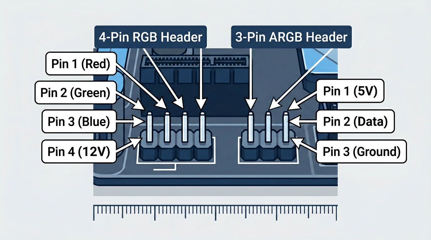
4-Pin 12V RGB Header (Standard RGB)
This is the older standard. The pinout goes: Pin 1 = Red (R), Pin 2 = Green (G), Pin 3 = Blue (B), Pin 4 = 12V. All four conductors in the rgb cable carry analog voltage signals. The microcontroller on the motherboard varies the voltage on each R, G, B channel to mix colors, similar to how a dimmable light fixture works.
The result: every LED connected to this header changes together. Same color, same brightness, same effect across the entire chain. You can’t tell one LED to go red while another goes blue. That’s the fundamental limitation of standard RGB.
Operating voltage is 12V DC. Most headers support up to around 2A of current draw, which translates to roughly 24W per header. An individual 12V RGB LED strip typically draws 0.2A to 0.5A per meter, so you have room for a few meters before hitting the limit. Check your strip’s spec sheet before daisy-chaining.
Physical keying: the connector has a blocked position where one pin would be, preventing you from inserting it backwards. The blocked position is on the side opposite Pin 1. If your connector has four conductors and slides in easily, Pin 1 should align with the board’s “12V” label. Not great if you ignore that label.
3-Pin 5V ARGB Header (Addressable RGB)
This is the current standard for modern builds. The pinout is: Pin 1 = 5V, Pin 2 = Data, Pin 3 = Ground. There’s no separate R, G, B channel. Instead, a single data wire carries a serial digital signal that individually addresses every LED in the chain.
The LED ICs used in ARGB components are most commonly WS2812B or SK6812. Each of these ICs sits inside the LED package itself and contains a tiny microcontroller. The data signal tells each IC exactly what red, green, and blue intensity to display at any given moment. That’s how you get a rainbow wave across a fan ring where every LED is a different color simultaneously.
Operating voltage is 5V DC. Most ARGB headers support up to 3A at 5V, giving you 15W of total power per header. At that budget you can typically run 60 to 120 LEDs before signal integrity starts degrading. Beyond that, you’ll see flickering or incorrect colors at the far end of the chain. According to Corsair’s ARGB vs RGB documentation, each LED in an ARGB system has its own IC that enables full programmable control over color profile, timing, and sync behavior, which is what separates it from standard RGB in practical terms.
The gap in the 3-pin connector is at what would be Pin 4’s position. That off-center notch is your physical safeguard. If the connector doesn’t fit, you’re at the wrong header type.
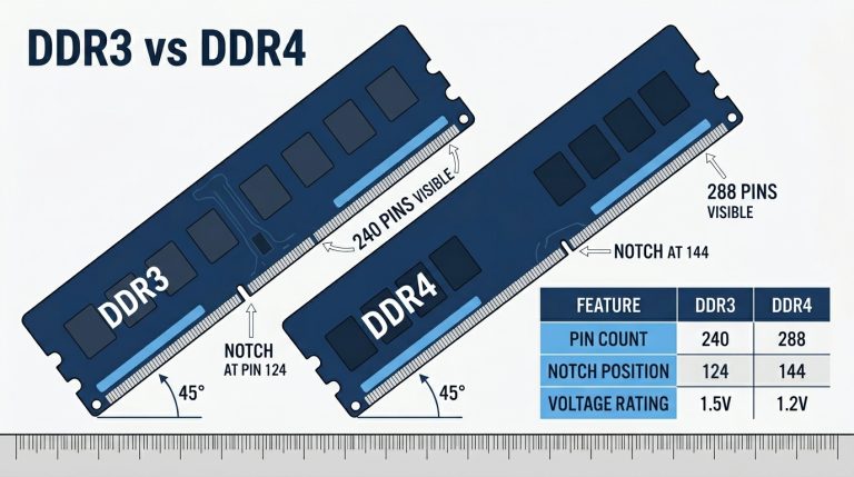
ARGB vs RGB: Side-by-Side Comparison
| Feature | 4-Pin 12V RGB | 3-Pin 5V ARGB |
|---|---|---|
| Voltage | 12V | 5V |
| Pin Count | 4 | 3 |
| LED Addressing | Synchronized (all same color) | Individual per LED |
| Color Control Method | 3-channel analog (R, G, B) | Single-wire digital data signal |
| Max Colors Per LED | ~16.8M (uniform across all LEDs) | 16.8M per individual LED |
| Effects Support | Limited (static, slow cycle) | Full dynamic (rainbow, reactive, music) |
| LED IC Standard | Common anode RGB | WS2812B / SK6812 |
| Max Recommended LEDs | Current-limited (~2A / 24W) | 60–120 LEDs per header |
| Compatibility Risk | 5V device in 12V header = destroyed | 12V device in 5V header = no function / damage |
| Typical Use | Older strips, budget fans | Modern fans, cases, cooler heads |
| Component Cost | Lower | Higher |
Brand-Specific RGB Header Names (ASUS, MSI, Gigabyte, ASRock)
This is where forum threads go sideways. Someone buys an MSI board and goes looking for the “ARGB header,” then can’t find it because MSI doesn’t call it that. The electrical specs are standardized industry-wide, but the label printed on the PCB is entirely up to the manufacturer. Here’s what each brand actually calls these headers:
| Motherboard Brand | 12V RGB Header Label | 5V ARGB Header Label |
|---|---|---|
| ASUS | RGB_HEADER | ADD_HEADER or AURA_GEN2 |
| MSI | JRGB1 / JRGB2 | JRAINBOW1 / JRAINBOW2 |
| Gigabyte | LED_C1 / LED_C2 | D_LED1 / D_LED2 |
| ASRock | RGB_HEADER | ADDR_LED |
| Biostar | JRGB | JARGB |
Regardless of what the silkscreen says, the rule never changes: 4 pins means 12V RGB, 3 pins means 5V ARGB. The MSI JRAINBOW header specification confirms the 5V/3-pin standard for their ARGB implementation, consistent with every other major manufacturer.
One thing to watch: budget boards from the B450, H410, and B510 era sometimes shipped with only one type of header. A board might have two JRGB (12V) headers and zero JRAINBOW (5V) ports, or vice versa. Always pull up the full spec sheet for your specific board model before purchasing RGB components. Don’t assume both types are present.
RGB Headers vs Fan Headers: Key Differences
This is the most common mistake new builders make. The headers look almost identical. A 3 pin fan connector and a 3-pin ARGB header are both small, three-pin connectors. A 4 pin fan connector and a 4-pin RGB header could pass for twins at a glance. They are not the same thing. Not even close in function.
3-Pin Fan Connector vs 3-Pin ARGB Header
A 3 pin fan connector carries three signals: 12V power for the fan motor, ground, and a tachometer signal that reports fan RPM back to the motherboard. The voltage is 12V and the header is labeled SYS_FAN, CHA_FAN, or similar.
A 3-pin ARGB header carries 5V power, a digital data signal, and ground. It has nothing to do with motor control. The physical difference you can feel: the ARGB header has a blocked-off notch at Pin 4’s position. Fan headers don’t have that block. You can also tell them apart by looking at the adjacent silkscreen, but in a dark case with a flashlight that’s not always easy.
Plugging a fan into an ARGB header won’t spin the fan. Plugging an ARGB component into a fan header risks incorrect voltage and signal damage. Neither direction is safe.
4-Pin Fan Connector vs 4-Pin RGB Header
A 4 pin fan connector (PWM) carries 12V, ground, a tachometer signal, and a PWM control signal for variable speed. These headers are labeled CPU_FAN, CPU_OPT, SYS_FAN, or CHA_FAN.
A 4-pin RGB header carries 12V, Red, Green, and Blue channel signals. No speed control. No tach. Completely different electrical purpose.
The physical key positions differ between the two connector types, but they’re subtle enough to miss under pressure. The blocked pin on an RGB connector is in a different position than on a PWM fan connector. When in doubt, check the manual. Always.
One more thing worth knowing: RGB fans have two separate connectors. A fan with RGB LEDs will have a 3-pin or 4-pin connector for the motor (goes to a fan header) AND a separate 3-pin ARGB or 4-pin RGB connector for the LEDs (goes to an RGB header). Both must be plugged in. Miss one and either the fan doesn’t spin or the lights don’t work.
How to Connect RGB to Your Motherboard (Step-by-Step)
Before You Start: What You’ll Need
- Your motherboard manual (download the PDF from the manufacturer’s support page if you don’t have the physical copy)
- The component you’re installing (fan, light strip, pump head, etc.)
- The product page or spec sheet for your RGB component confirming whether it’s 5V ARGB or 12V RGB
- System powered off, PSU switch set to off, and power cable unplugged
Anti-static precautions apply here the same as anywhere else in a build. Touch a metal part of the case before handling anything.
Step 1: Identify Your Component’s Connector Type
Count the pins on the cable’s connector end. Three pins mean ARGB (5V). Four pins mean standard RGB (12V). Check for a blocked or missing pin position, and cross-reference with the product documentation. If the spec sheet says 5V, it’s ARGB. If it says 12V, it’s standard RGB. Don’t guess.
Step 2: Locate the Correct Header on the Motherboard
Open the motherboard manual to the board layout page. Find the numbered component map and cross-reference it with the header name list. Using the brand name table from earlier, identify which header on your board matches the type your component needs.
Physically locate that header on the PCB. On most ATX boards it sits along the bottom edge, often between the front panel cluster and the SATA ports. On some boards, especially ITX, it may be on the right edge.
Step 3: Connect the RGB Cable
Hold the rgb cable connector so the blocked/missing pin position aligns with the keyed side of the motherboard header. For 12V RGB: Pin 1 on the cable (often marked with a small triangle or colored wire) must align with the “12V” or “R” label on the header. For 5V ARGB: Pin 1 must align with the “5V” marking.
Press the connector straight down onto the header pins. It should seat with light, even pressure. Fully seated. If it’s resisting, stop. Re-check orientation. Don’t force it. Bent pins on a motherboard header are a painful problem to fix.
Step 4: Configure in Software
After booting into Windows, install your board’s RGB control software:
- ASUS: Aura Sync
- MSI: Mystic Light
- Gigabyte: RGB Fusion 2.0
- ASRock: Polychrome Sync
Headers should light up with a default color effect as soon as the system reaches POST, before any software is installed. If nothing lights up at POST, that’s a signal to troubleshoot before installing software.
If your components aren’t from the same brand as your motherboard, or if you want unified control across mixed brands, OpenRGB is a free, open-source controller with broad hardware support. It bypasses proprietary software entirely and works with most WS2812B-based ARGB devices out of the box.
Expanding Your RGB Headers: Splitters, Hubs, and Daisy-Chaining
Most mid-range boards ship with one or two RGB headers and one or two ARGB headers. A premium Z790 or X670E board might give you three or four of each. Still not enough for a fully loaded build with six fans, a CPU cooler, and two light strips. Here’s how to expand.
RGB and ARGB Splitter Cables
A splitter Y-cable takes one header and branches it into two outputs. Both devices run on the same channel. Same pattern, same color, no independent control. That limitation is fine for most builds where you want uniform lighting anyway.
Current limits matter here. An ARGB header supports roughly 3A at 5V (15W total). Two devices sharing that budget get 7.5W each maximum, assuming equal draw. Before splitting, add up the total LED count of both devices. If you’re running two 40-LED strips, you’re well within limits. A six-fan chain on one splitter is pushing it.
For 12V RGB headers, the total budget is around 36W at 12V (3A). Individual LED strips typically draw 0.2–0.4W per LED, so you have more headroom here, but still worth calculating before chaining several meters of strip lighting.
RGB and ARGB Controller Hubs
A hub connects to a single header on your motherboard but breaks out into 6 to 10 individual ports. Every device plugged into the hub syncs through motherboard software the same as if it were directly connected. Popular options include the Phanteks PH-DRGB_HUB and various manufacturer-branded hubs from ASUS and Lian Li.
Hubs are also the right solution when you have no native RGB header at all. Some hubs connect via a USB 2.0 internal header instead of an RGB header, giving you software-controlled lighting even on older boards with no LED headers whatsoever. Worth the extra $20 if your board is header-limited.
What to Do If Your Motherboard Has No RGB Header
Common problem on budget B450, H410, H510, and older Z370-era boards. Not a dead end. Four workable options:
- Standalone ARGB controller: Products like the Corsair Lighting Node Core connect via an internal USB 2.0 header and control ARGB devices independently through iCUE software. No native RGB header required.
- Self-contained RGB components: Many fans and strips come with a bundled remote control and inline controller. No motherboard connection needed at all. No sync with system software either, but it works.
- USB-connected RGB hubs: These connect via USB 2.0 internal header and provide multiple ARGB/RGB ports. Some support partial software sync with workarounds.
- Upgrade the motherboard: If RGB sync matters to you and you’re on an older platform, factor native header support into your next board purchase. Even budget B650 and B760 boards include at least one ARGB header now.
Note that certain ecosystems like Corsair iCUE entirely bypass native motherboard headers and use USB connectivity for all lighting control. If you’re buying into a single-brand lighting ecosystem, check whether it even needs your board’s RGB header at all.
Troubleshooting RGB Header Problems
RGB LEDs Not Lighting Up At All
Start simple. Is the system fully booted? Most ARGB headers activate at POST, but a few boards hold lighting until Windows loads or until board software initializes. Wait for a full boot before concluding nothing works.
Then check:
- Is the connector fully seated? Press it down until it clicks or sits flush.
- Does the component require its own power connector from the PSU? Some larger RGB installations have a supplemental power cable that feeds the LED controller directly. Missing that means no lights regardless of header connection.
- Is the correct header type being used? A 5V ARGB component physically connected to a 12V header won’t light up (and may be damaged).
- Test with a known-working component on the same header to rule out a dead header.
RGB LEDs Showing Wrong Colors
Wrong colors almost always mean the connector is misaligned. One pin off. For a 12V RGB header, being offset by one position puts the wrong voltage on R, G, or B channels and produces a color that makes no sense. Unplug, re-align carefully, and reseat. Confirm Pin 1 matches the board’s marked position.
Also check that the cable itself isn’t damaged. A broken conductor in an rgb cable causes one channel to drop out, turning what should be white into yellow or cyan.
RGB Works But Won’t Sync With Software
The hardware is fine. The software side needs attention:
- Ensure manufacturer RGB software is installed and up to date.
- Check whether your component brand requires a specific plugin or profile. Thermaltake, be quiet!, and some Deepcool products need brand-specific plugins for Aura Sync or Mystic Light.
- Try OpenRGB as a fallback. It handles mixed-brand setups better than any single manufacturer’s software.
- Check the BIOS. Some boards have a “Stealth Mode” setting or an LED disable option that overrides software control. Search for “LED” in your BIOS settings and make sure lighting isn’t disabled at the firmware level.
RGB Header Physically Damaged or Missing
Bent pins happen. Power off and unplug the system. Use a fine-point tool (a pin, a toothpick, or a mechanical pencil tip with no lead) to very carefully straighten the bent pin while keeping the PCB still. Don’t apply lateral pressure. Straight down, gently.
If the header is absent entirely because the board doesn’t have one, that takes you back to the controller and hub options covered in the previous section.
FAQ: RGB Headers on Motherboards
What is the RGB header on the motherboard for?
An RGB header powers and controls the LED lighting on compatible PC components like fans, light strips, and coolers. It supplies voltage to the LEDs and carries the control signal that lets motherboard software change colors and lighting effects. It is not a power or fan header and serves no other function.
How do I find the RGB header on my motherboard?
Check your motherboard manual’s board layout diagram and search for headers labeled RGB, ARGB, JRGB, JRAINBOW, ADD_HEADER, D_LED, or ADDR_LED depending on your board’s brand. Physically, these headers are typically along the bottom or right edge of the PCB. The silkscreen label printed next to the header on the board itself also identifies it.
Which header do I use for RGB fans?
RGB fans have two separate connectors and both need to be connected. The 3-pin or 4-pin fan connector (for motor power and speed control) plugs into a SYS_FAN or CHA_FAN header. The RGB or ARGB lighting connector plugs into the matching RGB or ARGB header. Connect both, or the fan either won’t spin or won’t light up.
Can I plug an ARGB device into an RGB header?
No. A 5V ARGB device connected to a 12V RGB header will receive more than twice its rated voltage. That permanently destroys the LED ICs in the component. The headers are physically keyed differently for a reason. Always confirm the voltage of your component before connecting it.
What if I have more RGB devices than headers?
Use an RGB or ARGB splitter cable to run two devices from one header, keeping in mind both devices will show the same color output. For independent control of multiple devices, an ARGB hub (such as the Phanteks PH-DRGB_HUB) expands one header into 6 to 10 ports while maintaining full software sync. For boards with no native RGB header, a USB 2.0 internal header-connected controller handles lighting without any dedicated RGB header at all.
Final Thoughts
The rule is straightforward: 4-pin 12V for standard RGB, 3-pin 5V for ARGB. Never mix the two. Every other decision, from brand-specific header names to splitters and hubs, flows from understanding that one distinction. Before you connect anything, pull up the manual. Confirm the header type. Confirm your component’s voltage. The 30 seconds that takes is a lot cheaper than replacing a dead fan or light strip.

Alex has been building and tweaking custom PCs for over 12 years. From budget builds to full custom water loops, he’s assembled more than 50 systems and helped hundreds of builders troubleshoot their rigs. When he’s not benchmarking the latest hardware, you’ll find him optimizing airflow setups or stress-testing overclocks.